• When you click on links to various merchants on this site and make a purchase, this can result in this site earning a commission. Affiliate programs and affiliations include, but are not limited to, the eBay Partner Network.

Noticed Steering Column getting hot on 70 RR

Dragon Slayer

Well-Known Member
Local time
4:20 PM
Joined
Jun 18, 2014
Messages
1,016
Reaction score
486
Location
Virginia
4spd car and I noticed that the column case just below the steering wheel gets warm to hot when driving. Lower end of column is cool. The electrical is positioned under this area. Is this normal? Not sure what can cause that amount of heat without some sort of failure of the electrical controls in the steering column. Any ideas? G
 
your ignition switch is probably worn out. too much resistance and heat is the result at the weakest point. the wire or connection.
 
^^ That. The igntion switch had high resistance and is in the process of melting the wire and connector insulation. This not something to mess around with....it wil at the least take you off the road if not worse.

You need to get at the ignition switch and connector and examine them for melting.....and get a new ignition switch on order. If you are not wanting to do this yourself, get it done very soon.

BTW where are you in VA if I may ask?
 
Agreed, won't hurt to examine the ignition. How did this come to your attention? Some things are not noticed for years. Put a digital thermometer on it and have someone else with a 70 do the same.
 
Thanks guys. New to me car, and I have been going through it. The reverse linkage lock out is not connected so I had to rotate the column. When I touched it thought it was not normal. I am in South East VA, near the beach. G
 
OK, too far for me to stop in; I'm up in the Blue Ridge Mtns. IMO no need to check the temp; this is abnormal, and it will progressively get worse. The heat is due to increased contact resistance, and causes a voltage drop to all sorts of systems in the car, like the ignition system. It also lowers the voltage to the voltage regulator (fed by the same circuit as the igntion) and that usually makes the alternator raise its charge voltage.

If you are not aware of it, then bulkhead connectors are another good source of problems; the whole battery charging current from the alternator, and all the interior circuits, lights, etc., goes back and forth through a couple of contacts (the 2 larger wires going in/out of the bulkhead connectors). This is another classic spot for corrosion, overheating, and melting.
 
Thanks, So how hard is it to get to the ign switch? Can you give me any other specific areas to look at? Before I went to get the car, the engine harness got damaged and had to be replaced. Was told the harness shorted out on the block. Currently everything seems to work fine, all exterior and interior lights, dash and gauges. The only quirks when I was doing brake petal work, I was able to touch a vent control and had the horn beep, but I can't repeat this now and when I turn the turn signals on occasionally both hood mounted indicators will flash even though the externals are correct. I think there must be insulation damage in the wire running to the hood lights. The amp meter goes high at start up but goes back to a normal reading in a few seconds. Gas tank gauge only reads 3/4 at full tank, but temp gauge reads correct. G
 
The bulkhead connectors, ammeter, and the ignition switch are common places for issues. Here is a thread for igntion switch replacement in a Dart that ought to be very similar:
http://www.forabodiesonly.com/mopar/showthread.php?t=128836

Ammeters can be fine or can be a significant problem: an inspection of the threaded terminals on the back of the instrument cluster is needed to look for any discoloration or signs of heat.

I don't want to be overly dramatic, but the reality is that if there are issues in these 3 areas not tended to, these can cause opens and a dead car, or shorts. (On rare occasions, a fire can get going.....) Start by examining the bulkhead connectors inside and out; if you see any sign of plactic warpage, then IMO it needs attention right away.

Your other erratic connections sounds like what you have diagnosed: some damaged insulation in places; you need to get to the harness all over and look. The blinker indicator thing could be in wiring or in the column switch alone; the latter would be less troubling.

The ammeter behavior sounds normal.
 
The amp gauge wire runs through the steering colum. I would rewire/reroute the amp gauge wire to remove it from the steering colum. Do a visual of the bulkhead connectors on both sides.
Chances are once you unwrap some wires,overheated wires will be found.:blob1:
 
Great help, thank you. I did a quick inspection today and everything looked fine. No signs of damaged connectors or melted insulation. I can get to the steering column connectors easily, so I guess I can unplug them and measure the resistance into the switch and see what the readings are. The only lights that flash together are the hood lights. The actual front and rear turn signals work fine. If I open the hood, the dual flashing goes away. So I guess I need to look closely where the 2 wires are merged. G
 
Update on what I found

Ok, I found some damaged wires. Here is what I have. I disconnected the ignition switch harnessconnector under the dash. I noticed that the battery feed (red) had some minorinsulation swelling on the instrument harness side of the connector and the J2 (DarkBlue) wire which feeds the ignition system components is seriously damaged onthe instrument harness side. TheIgnition switch side of the connector wires look good as far up the harness asI can see. So I tested the resistance throughthe connector and the battery feed through the switch and to the accessory wire,ballast jumper and starter wires all read 0 ohms. The resistance through the switch to the J2wire (one that is damaged on the opposite connector) is about .3 to .5 ohms. Could this generate the problem? The damaged wire on the instrument harness sidegoes right to position N on the bulk head mount. I can see that much of the wire insulation isdamaged. It also feeds the Key headlightbuzzer (not sure where it is, but I don’t think it is working if the roadrunnerhad this feature and the G5 wire for the voltage limiter circuit (gauges seem to workfine). The mean load on this is the wire that feeds(via Number one Splice) the ballast resistor, voltage regulator, and alternatorfield in the engine compartment. So Iwonder if this damage was caused by the.3-.5 ohm resistance in the ignition switch, or if this is damage from theengine wire harness issue that the previous owner had and the trouble shootingthat was done. Apparently previous ownerswapped a regulator and alternate. Ichecked all the engine compartment wiring and hook ups and they are correctwith 0 ohm in the wires and no damage I can see at the engine compartment bulkhead connection.

So is .5 ohms too high a resistance in the switch?
Does the roadrunner have a buzzer for keys headlights on?
Any other things I should check, or should I rewire thisdamaged wire and see if my heat source in the column goes away?

I appreciate all the help I have received. G
 
Absolutely this is a problem; that is a LOT of resistance for a straight piece of wire or an ignition switch contact. The current in the dark blue wire is such that it will generate about 5-10 watts of heat across that resistance. And realize that as this heats up, the resistance will get higher, and so it is a self feeding issue (a form of thermal runaway). Actual new resistances should be in the range of a few hundredths of an ohm.

It would not surprise me that the wire insulation could have been burned by a short in the engine compartment. But, the ignition switches are a a well known problem area, and what you are finding is a classic case. This switch is ready to be pitched.

Additionally, the wire can be hardened (annealed) due to heating and have higher resistance due to that, and will be more prone to break under vibration. So the wire needs to be replaced too. The red wire into the ignition switch is a concern for that reason as it carries a lot of current at times.

It is good that the bulkhead connectors look good. Those should be cleaned and the contacts re-treated with dielectic grease.

Have you checked the ammeter connections to see if there is any discoloration or other signs of heat?
 
Well...... I though this would be a winter project, not the prime cruising season. The column has been lowered, the rally dash is removed and I have unwrapped the dash harness to inspect the wires and remove the damaged blue wire. On the interior side of the bulkhead connection I found about 5 splices that were just wire wrapped. I intend to solder and heat shrink those connections. The blue wire has been traced all the way to the 3 way splice (looks like a factory compression/spot weld of the wires). So I have about 3 feet and 2 feet of wire to replace. Are the plug connectors and flat blade female connectors readily accessible at a store? If so anyone know the part number type (not MOPAR number). Where is the best place to get a new switch? Should there be a headlight/key buzzer, think one is under the dash. Will add a picture later. G
 
Don't use the flat blade connectors use a bullet connectors... drill a hole through the connector and run a wire through it... the original style blade connectors are the problem from sq 1
 
Well it is a good thing that you are getting to this or your cruising season might have been short(ed)! I ususaly go with NAPA Echelin electrical parts but there may be better that others can suggest for this ignition switch.

I believe I read that the flat connector/spades in the bulkhead connecotrs are Packard 56 types. If you replace the high current ones (large wires), I would try to get a little silver loaded terminal grease, that significantly lowers any resistance. Apply it sparingly.

The connector terminals at the column connector may be different types.

Solder is good as long as you:
1) Clean the soldered joints with straight alcohol to get the residual flux off; flux will corrode the wire (it is supposed to eat away oxides but will keep going!) and also absorbs moisture
2) Support them really well with heat shrink and tape into the harness for support. Unsupported wires that are soldered tend to anneal and break with vibration right where the solder ends.
 
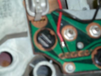
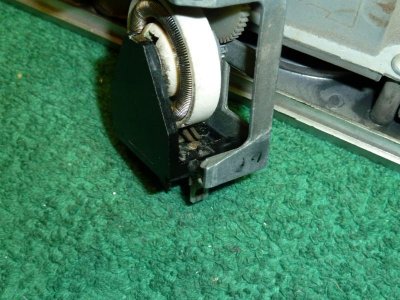
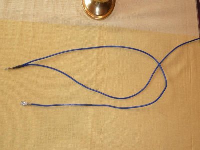
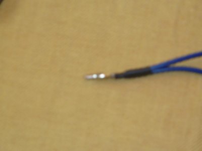
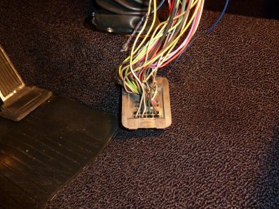
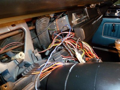
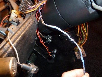
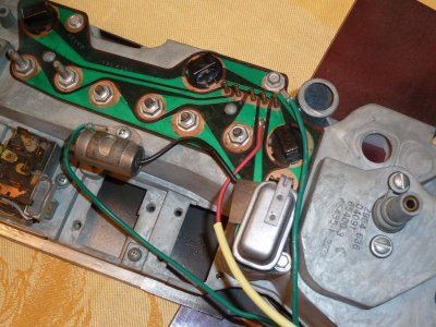
Here are some pictures and additional mods I am making. You can see the damaged wires. The ignition wire is the return of Battery feed through the ignition switch to position N of the bulkhead terminal block. The main load is the ignition system ballast resistor to coil, Voltage Regulator and Alternator Field. This wire also feeds the Key in buzzer and the Emergency brake/Brake warning light. For some reason Mopar decided to take the 16ga wire coming out of the column harness and route it all the way into the instrument harness at a point to splice for feeding the buzzer and light wire. Than returning with 16ga wire through the harness and to the Bulk Head terminal N. This adds about 2ft of extra 16ga wire and a splice between the source of the power and the main load. So I constructed a custom lead that will route the 16ga from the column connector directly to terminal N while also feeding 16ga to the splice point for the buzzer and light bulb. This shortens the length of wire for the main load and removes the splice point. I am sure when the ignition wire shorted to the block in the engine compartment the load caused all this wire to heat up and melt the insulation. Luckily when I peeled away the wire, the insulation on the other wires in the harness were not damaged. Otherwise this would have been a $1000 repair with a new instrument harness. Turns out the steering column connection is a bullet connector. I was able to get one from RS that was a 20 amp exact match. The terminal in the N slot had started to fuse to the plastic. I had to work to get it out without too much damage to the block. This is a typical 1/4 female blade connector with a locking tab on the back. While I had it apart I was able to see why my tach was fluctuating when the turn signals were on. The tach is an E body 8K RMP tach that the previous owner added. He spliced into the Accessory power lead that feeds the turn signals via the flasher. Unfortunately he made a mistake and put it on the output of the flasher instead of the input. I decided to power it directly from the 12V accessory source that feeds the dash. I did this by soldering on the printed trace. This way I don't have to unscrew a tach power lead too when removing the instrument panel. I also decided to add an additional instrument panel ground that I can attach in to the dash frame. I also was having issues with the dimmer switch turning on the dome light. Turns out there was a lot of dirt and some corrosion. This was easy to clean with some fine sandpaper and deoxit to clean contact button and fingers. I also cleaned the resistor wire and contact brush. Will repair my other joints and reassemble the harness and instrument panel. G
 

Attachments

  • P1000366.jpg
    P1000366.jpg
    34.4 KB · Views: 145
  • P1000367.jpg
    P1000367.jpg
    80.8 KB · Views: 161
  • P1000368.jpg
    P1000368.jpg
    85.8 KB · Views: 152
  • P1000369.jpg
    P1000369.jpg
    16.8 KB · Views: 155
  • P1000370.jpg
    P1000370.jpg
    122.9 KB · Views: 145
  • P1000371.jpg
    P1000371.jpg
    82.5 KB · Views: 144
  • P1000372.jpg
    P1000372.jpg
    71.2 KB · Views: 175
  • P1000373.jpg
    P1000373.jpg
    86.6 KB · Views: 139
Auto Transport Service
Back
Top