The older Mopar systems are one of the simplest in the industry, and the change in 70 and later is about "next."
First do yourself a favor, if you have not, waltz over to "MyMopar and download a free service manual. Electrical is Chapter 8
http://www.mymopar.com/index.php?pid=31
This page
http://www.mymopar.com/index.php?pid=78
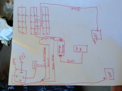
has a simplified diagram of "what you have"
The alternator you pictured is a "modification" of a 70 and later. The CHANGE between 69/ earlier and 70 /later is that the later one has TWO field terminals, where the 69 has only one. On the earlier ones, the second field brush is grounded "permanently."
So your FIRST job is to take your multimeter and make sure the brush at the top of your photo is actually grounded to the case. Put one lead on the alternator case with the meter set for resistance (ohms). Put the other probe on the field terminals one at a time. The one WITH the "push on" connector tab should show "a few" ohms, and the other should show a dead short, IE zero ohms
In your photo, the grounded one (zero ohms) is the one at the top of the photo.
++++++++++++++++++++++++++++++++++++
Next think in "sections"
1....The parts, the regulator and alternator. "New" by the way does not mean "functional."
2....The field circuit, IE the switched ignition run power feeds to the voltage regulator IGN terminal (push on) and the screw terminal (green) of the VR goes to the insulated field terminal of the alternator.
3....The output circuit. This is the great big thick stud / nut and black wire, which feeds the output of the alternator through the bulkhead, through the ammeter, back out the bulkhead, and to the battery.
+++++++++++++++++++++++++++++++++++++++++++++
Let's make a couple of easy tests. There are several ways to proceed
1.....Remove the green "push on" field wire at the alternator. Hook a "clip" alligator lead to the disconnected alternator terminal. Run this wire to "battery" that is the big huge stud on the starter relay. Touch it a few times in subdued light and listen. you should see and hear a small spark.
Start and run the engine, slowly bring up RPM. Watch the ammeter. It should start to charge. If not, take your multimeter and hook it up to the battery. Again bring up RPM. It should start to bring the battery voltage up, depending on how far discharged it might be.
If the voltage does not rise, and stays down around 12.5, hook your meter over onto the large output stud on the alternator. Again bring up RPM. If it rises WAY up say, above 18V, there is a break in the output charging wire somewhere. Bad connection in the firewall connector, problems in the ammeter, etc
If the voltage does NOT rise, and stays down around 12.5 or below, it is NOT charging. RE check that the field circuit is getting power. In order to do that you need to measure field current. Post the brand and model (or photo) of your multimeter, I can tell you how.
What you want to determine, is if with the clip / alligator lead hooked to battery, that the field is getting power AND is drawing 3-4 amps or so.
Post back........................
++++++++++++++++++++++++++++++++++++++++++++
2.....If the above test DOES result in the ammeter showing charge, this shows that the alternator is capable, and that the field (brushes) are getting power and grounded on one of them.
Now let's check the field circuit. Hook the green field wire back up to the alternator. Disconnect both wires at the VR. Jumper these two wires together. Run the engine, and again see if the ammeter shows charge.
If it does...........make absolutely CERTAIN that the VR is grounded. Don't just look at it. Scrape paint / rust away around the bolt holes, and the back of the VR mounting, and mount tight using star lock washers. Re-connect it and see if the system charges.
If not.........replace the VR
- - - Updated - - -
Also you appear to have some form of HEI type ignition. The ballast resistor would have been bypassed. Do you know what the relay is for, below the VR? It might be supplying ignition power, that is the key might be triggering the relay, and the relay supplying power to ignition and the VR