gottagettamopar
Well-Known Member
After poking around under the hood trying to figure out where my horn wiring was and how to install a windshield washer pump, both of which are required for UK road worthiness, I found part of the lighting loom had fused and an unhealthy amount of mismatched wires, connectors and other nasties. The closer I looked, the less I liked what I saw. It ran but I was sure there was some potentially hazardous wiring that needed correcting.
After some web browsing I kept coming back to Mark Hamiltons, MAD Electrical website. After speaking to Mark I ordered his Trunk Mount Kit, New System Kit and Start 'M Up Kit. Mark was more than happy to answer all my questions which was great because I'm no expert at wiring and his kits are aimed more towards GM.
In addition to the MAD kits I also bought some original type 56 terminals, several different colour cables in a couple of sizes to match the original loom, heat shrink tubing, butt connectors and ring terminals.
As per Mark's advice, I crimped, soldered and heatshrunk all joints.
The Chrysler starter relay and starter solenoid have to be worked around but the basic principles of improving performance of headlights, the starting circuit and general power distribution are the same.
My battery was already trunk mounted, I had MSD, a solid state ballast resistor, no horn wiring, no fan relay and a jumper across the terminals on the firewall connector that bypassed the standard amp meter in the dash. I'm lucky enough to have the upgraded heavy duty firewall connectors for the main power lead going to the dash, so I used these instead of drilling the connector and passing an 8 gauge wire through the connector, as per the MAD upgrade.
I unwrapped everything under the hood and made a diagram of what was there for future reference.
I then removed all of the electrical accessories and refitted them in more appropriate positions within the engine bay. I was rewiring, so I didn't need to keep them where they were. I was also adding two junction block terminals for power distribution, horn wiring, windshield washer pump and reservoir and relays for the headlights and fan. So I needed to move things around anyway.
I wasn't aiming for a restoration quality look but I did want it to look neat and tidy and I wanted to minimise the number of cables hanging over and around the engine.
I made a new diagram of what I would end up with, including the various upgrades. I found this much easier to follow and I could just make up each new cable and add it to the car one at a time.
I used existing holes to mount everything in the firewall, inner wings and rad support wherever possible and there were plenty of them to chose from! Where holes were too big for my purposes, such as where I wanted P clips to hold the loom, instead of the whacking great bolt that a previous owner had added, I used a rivnut to give me a neat threaded hole.
I reckon this took me about 30 hours to complete but I now have much better cranking when starting up, brighter headlights, a horn, a fan working correctly, a washer pump and power distribution hubs at the firewall and the radiator support.
Here are some pics of the job.
Lighting harness was fused.
View attachment 141975
Existing wiring unwrapped to expose nasties.
View attachment 141954
Electrical components relocated.
View attachment 141924
View attachment 141925
Headlight relays, horn relay and junction block on the radiator support.
View attachment 141926
Rivnuts used to secure P clips.
View attachment 141939
Washer reservoir and pump.
View attachment 141929
Cables running from battery in trunk. I made up a small plate to cover a large hole and added grommets.
View attachment 142000
Remote solenoid in trunk next to battery. Battery positive is wired direct to the starter main stud. The cable on the small stud of the starter is wired to the "S" terminal on the remote starter solenoid. A battery charging cable runs from the junction block or starter relay to the battery positive stud on the remote solenoid.
View attachment 141944
Jumper cable across the starter terminals.
View attachment 141943
Fan relay and two headlight relays with the horn relay and junction block all wired up on the radiator support. The additional junction block up front means that you can run short power feed lines to the relays and accessories. The junction block has the fusible links attached to it at bottom right.

Firewall connector with jumper cable across the heavy duty terminals.
View attachment 141940
High and low tone horns wired up. I had to bend the terminals on the horn by 90 degrees to get them pointing up and away from the core support.
View attachment 141938
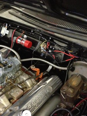
Pretty much complete.
I only attached one main cable on the starter relay stud and this jumped to the adjacent junction block. The heavy blue cable runs from the remote solenoid in the truck. The yellow cable goes to the firewall connector terminal C. The brown cable is the neutral safety switch.
All power distribution cables run from the junction block and it also powers accessories.

Ignition components mounted along the firewall. MSD is just out of sight at bottom left.
Alternator charging cable runs along the top of the valve cover and runs to the junction block.

- - - Updated - - -
Not sure why pics are not posting, I'll try and correct.
- - - Updated - - -
Lighting harness fused.

Existing wiring unwrapped to expose nasties.


Electrical components relocated.

Headlight relays, horn relay and junction block on the radiator support.

Rivnuts used to secure P clips.

Washer reservoir and pump

Cables running from battery in trunk through the firewall. I made up a small plate to cover a large hole and added grommets.

Remote solenoid in trunk next to battery. Battery positive is wired direct to the starter main stud. The cable on the small stud of the starter is wired to the "S" terminal on the remote starter solenoid. A battery charging cable runs from the junction block or starter relay to the battery positive stud on the remote solenoid.

Jumper cable across the starter terminals.

High and low tone horns wired up. I had to bend the terminals on the horn by 90 degrees to get them pointing up and away from the core support.

Sorry for the two part post. Had trouble loading images. Hope this makes sense.
After some web browsing I kept coming back to Mark Hamiltons, MAD Electrical website. After speaking to Mark I ordered his Trunk Mount Kit, New System Kit and Start 'M Up Kit. Mark was more than happy to answer all my questions which was great because I'm no expert at wiring and his kits are aimed more towards GM.
In addition to the MAD kits I also bought some original type 56 terminals, several different colour cables in a couple of sizes to match the original loom, heat shrink tubing, butt connectors and ring terminals.
As per Mark's advice, I crimped, soldered and heatshrunk all joints.
The Chrysler starter relay and starter solenoid have to be worked around but the basic principles of improving performance of headlights, the starting circuit and general power distribution are the same.
My battery was already trunk mounted, I had MSD, a solid state ballast resistor, no horn wiring, no fan relay and a jumper across the terminals on the firewall connector that bypassed the standard amp meter in the dash. I'm lucky enough to have the upgraded heavy duty firewall connectors for the main power lead going to the dash, so I used these instead of drilling the connector and passing an 8 gauge wire through the connector, as per the MAD upgrade.
I unwrapped everything under the hood and made a diagram of what was there for future reference.
I then removed all of the electrical accessories and refitted them in more appropriate positions within the engine bay. I was rewiring, so I didn't need to keep them where they were. I was also adding two junction block terminals for power distribution, horn wiring, windshield washer pump and reservoir and relays for the headlights and fan. So I needed to move things around anyway.
I wasn't aiming for a restoration quality look but I did want it to look neat and tidy and I wanted to minimise the number of cables hanging over and around the engine.
I made a new diagram of what I would end up with, including the various upgrades. I found this much easier to follow and I could just make up each new cable and add it to the car one at a time.
I used existing holes to mount everything in the firewall, inner wings and rad support wherever possible and there were plenty of them to chose from! Where holes were too big for my purposes, such as where I wanted P clips to hold the loom, instead of the whacking great bolt that a previous owner had added, I used a rivnut to give me a neat threaded hole.
I reckon this took me about 30 hours to complete but I now have much better cranking when starting up, brighter headlights, a horn, a fan working correctly, a washer pump and power distribution hubs at the firewall and the radiator support.
Here are some pics of the job.
Lighting harness was fused.
View attachment 141975
Existing wiring unwrapped to expose nasties.
View attachment 141954
Electrical components relocated.
View attachment 141924
View attachment 141925
Headlight relays, horn relay and junction block on the radiator support.
View attachment 141926
Rivnuts used to secure P clips.
View attachment 141939
Washer reservoir and pump.
View attachment 141929
Cables running from battery in trunk. I made up a small plate to cover a large hole and added grommets.
View attachment 142000
Remote solenoid in trunk next to battery. Battery positive is wired direct to the starter main stud. The cable on the small stud of the starter is wired to the "S" terminal on the remote starter solenoid. A battery charging cable runs from the junction block or starter relay to the battery positive stud on the remote solenoid.
View attachment 141944
Jumper cable across the starter terminals.
View attachment 141943
Fan relay and two headlight relays with the horn relay and junction block all wired up on the radiator support. The additional junction block up front means that you can run short power feed lines to the relays and accessories. The junction block has the fusible links attached to it at bottom right.
Firewall connector with jumper cable across the heavy duty terminals.
View attachment 141940
High and low tone horns wired up. I had to bend the terminals on the horn by 90 degrees to get them pointing up and away from the core support.
View attachment 141938
Pretty much complete.
I only attached one main cable on the starter relay stud and this jumped to the adjacent junction block. The heavy blue cable runs from the remote solenoid in the truck. The yellow cable goes to the firewall connector terminal C. The brown cable is the neutral safety switch.
All power distribution cables run from the junction block and it also powers accessories.
Ignition components mounted along the firewall. MSD is just out of sight at bottom left.
Alternator charging cable runs along the top of the valve cover and runs to the junction block.
- - - Updated - - -
Not sure why pics are not posting, I'll try and correct.
- - - Updated - - -
Lighting harness fused.
Existing wiring unwrapped to expose nasties.
Electrical components relocated.
Headlight relays, horn relay and junction block on the radiator support.
Rivnuts used to secure P clips.
Washer reservoir and pump
Cables running from battery in trunk through the firewall. I made up a small plate to cover a large hole and added grommets.
Remote solenoid in trunk next to battery. Battery positive is wired direct to the starter main stud. The cable on the small stud of the starter is wired to the "S" terminal on the remote starter solenoid. A battery charging cable runs from the junction block or starter relay to the battery positive stud on the remote solenoid.
Jumper cable across the starter terminals.
High and low tone horns wired up. I had to bend the terminals on the horn by 90 degrees to get them pointing up and away from the core support.
Sorry for the two part post. Had trouble loading images. Hope this makes sense.