• When you click on links to various merchants on this site and make a purchase, this can result in this site earning a commission. Affiliate programs and affiliations include, but are not limited to, the eBay Partner Network.

ez wire harness issues with ign/start

RoadWarrior

Well-Known Member
Local time
7:56 PM
Joined
Nov 15, 2011
Messages
87
Reaction score
18
Location
Santa Cruz
Hey guys. Been gone awhile. New job, moving, all that fun stuff. Got my 67 Belvedere "Hellvedere" out and began to rewire it. I am using the EZ wire 21 circuit harness because it was really cheap. Removed all the fuses and wires I don't need. I know its an overkill but you never know what I will add down the road. Anyway here is my question:

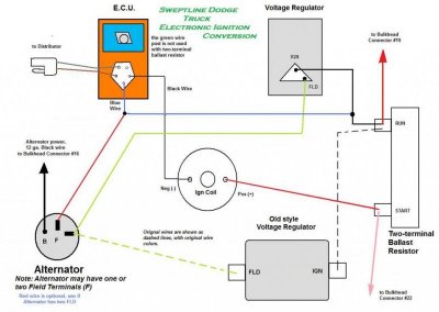
I have a 60amp duel field alternator. Brand new electronic voltage regulator. 4 wire orange ecu with 2 peg ballast resistor. Ign peg from the voltage regulator is spliced to alternator field, ign #1 and blue wire from ecu. other field on volt reg to other field on alternator. Now before Ign#1 on the switch went straight from switch to Ball. Res. But with the new harness the coil wire goes through the fuse box then to the ballast resistor. Now key on to acc I have 12 volt to voltmeter. Turn key other way to run position I pop the 30 amp fuse everytime. I have 12.26 volts from ign 1 with key in "run". I never had a fuse before should I bypass fuse box and run it straight to the ballast resistor? My ign #2 goes straight to positive side bypassing coil as it should.

All I can think of are the "universal" wires I won't be using. I made sure nothing is touching ground. Also there is the alternator exciter wire I did not connect to alternator because I am already using the 2 field terminals. Should I use this to splice into voltage regulator instead of my ign#1 for the 12 volt source? there is a 10 gauge "solenoid power" wire from fuse box I am not using because mine gets power straight from battery. I am assuming it means starter solenoid. "Alt power" to battery post on starter relay for fuse power.

I ignored the instructions that came with it. They made no sense. I drew up my own but didn't expect to blow my coil fuse over and over. Now my car did start having problems in the Run position which started this project (bulk head was a mess). So maybe bad ign switch? Any thoughts? like I said when I switch the key to run (not start) I have 12.26 volts on the ign #1 post on my voltmeter.

Hope that wasn't to long. I am on disability for a broken wrist so have nothing but time. Thanks again guys.
 
sounds like a there's a number of different issues here. Can you post any pics?
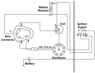
Here's a basic diagram of how the ignition portion should look like. I would trace each wire carefully and create a sketch of the way you find it and then compare to the way it should be for a 73 & up system and the diagram you received with the new wiring.

ignit1a.gif
 
I understand that fine, but where does the voltage regulator splice in? I assume ign #1? Thats how it was before on both my 67 and my 74. And thats what I did here. But when I find a diagram of the charging system it shows ignition 1 to regulator. So am I safe in assuming ECU #1, ign #1, and ignition from voltage regulator all splice together then connect to ballast resister? Ive read someplaces it doesnt matter what the 12 volt source is for ignition side of voltage regulator, as long as it gets its voltage.

And am I correct that the alternator exciter wire is not used? Never had one before, but I've also never used a modern harness before. And the solenoid power 10 gauge from fuse box? Do I also ignore? Or should I run it to starter solenoid anyway so it has a path, even though it gets power direct from battery? I know with a 80 amp or higher alternator they recommend an extra bypass wire from alternator to starter. But im not cranking the engine yet. I want to get passed my blown coil fuse. Maybe mopars dont like a fuse on the ign #1?

Thanks!!
 
You ever thought about using this as an excuse to upgrade the system to an alternator with a built in regulator or maybe even a 1 wire alt? Most universal harnesses are based off newer equipment like the HEI ignitions and not for Mopars although you can definitely make it work, just makes sense to me to get rid of the the ballast and external regulator? I also used a universal harness and have almost no wires in the engine bay just by switching out the ignition and going to a 1 wire alt. Just a thought.
 
X2 747

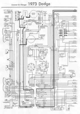
to help with this, here's a '73 schematic from a B body.
73CoronetChargerA1.jpg

You can see that the ign side of the regulator connects to the ballast and to what I think in #1 on the ECU although the terminals are not clearly shown on this diagram.

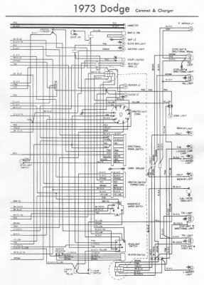
73CoronetChargerB.jpg

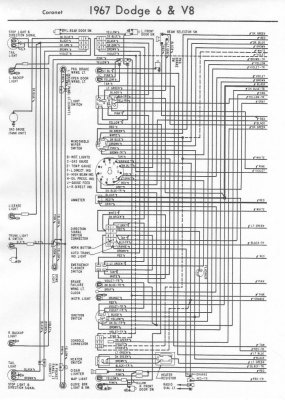
I can't say which contact point is #1 on your IGN switch. The 67 schematic shows a Brown and DK Blue going to the IGN switch.

67CoronetA.jpg
 
Well I have everything correct. Only difference is I am not using the ammeter and all the extra acc wires from fusebox I am not using. Should I remove the fuses? Or keep them in and cap the wires? I feel like removing the fuses is the best method. This wouldnt overload the fusebox would it? If anyone else installed a new harness would love to know what you did with the solenoid power and alt exciter wire. I have all these wire diagrams and they work great, but they are for a car with stock harness. Stock harness did not have solenoid power or alt exciter. this is the question I can't seem to get an answer on. Does new harness require extra ground somewhere?

Maybe I am confusing people? I've never had an issue with stock harness/fusebox. Rewired a few old mopars no issues. Its this new harness with all these extra wires I am not familiar with. I am assuming it's geared more towards a standard GM setup. So what to do with the unused wires/fuses without causing an issue.

- - - Updated - - -
 
sorry, this takes time so slow responses. two different wiring systems merging together which is spread out over 4 schematics and trying to dissect your questions...on two screens lol (I prefer paper)

okay now I need a 5th screen...lol

so, starting with the run side of your photobucket dia., looks correct but depends on where it's connected to the ign switch. the 67 schematic shows this as a DK Blue w/tracer and should connect in the same location as before.
 
You ever thought about using this as an excuse to upgrade the system to an alternator with a built in regulator or maybe even a 1 wire alt? Most universal harnesses are based off newer equipment like the HEI ignitions and not for Mopars although you can definitely make it work, just makes sense to me to get rid of the the ballast and external regulator? I also used a universal harness and have almost no wires in the engine bay just by switching out the ignition and going to a 1 wire alt. Just a thought.


Ya I thought about that. Sucks I just bought this alternator. But I would like to get it running at least just for my own knowledge before hooking up a one wire alternator. maybe to coil fuse is somehow getting voltage from both sides with key in run? I'll have to check the coil side connection with ign 1 removed. seems like a good starting point.

- - - Updated - - -

elecignmopar.jpg

here is how I have it so far. Except ign#1 goes through the fuse box instead of directly off ign switch. (wire to bulkhead connector #19)

elecignmopar.jpg
 
I'm wondering if the problem is mixed up connections on the ign switch? Otherwise the diagram looks fine.

The other thing I noticed is that on our pre-70 systems, one of the alt terminals is a gnd terminal, not a field terminal. This changed in 1970 I believe. Was your system on the 67 wired like a 1970?
 
sorry, this takes time so slow responses. two different wiring systems merging together which is spread out over 4 schematics and trying to dissect your questions...on two screens lol (I prefer paper)

okay now I need a 5th screen...lol

so, starting with the run side of your photobucket dia., looks correct but depends on where it's connected to the ign switch. the 67 schematic shows this as a DK Blue w/tracer and should connect in the same location as before.


Yes, before the blue wire w/ tracer connected through bulk head to ign 1 On ign switch. With bulk head removed it would be a direct path from run position of ballast resistor to ign #1 terminal on switch. The only thing I am doing different is from run position it goes through a 30amp fuse, then to ign switch. This is the fuse that keeps blowing. I am thinking this fuse is more for modern cars and I should just stick to a direct path from ign 1 (run) to run side of ballast resistor? This is my main question I was hoping to answer before attempting. Would rather blow a fuse then burn a wire if there is an issue. I realize most this harness is to be ignored for my 74 era mopar ignition.

I just liked the idea of sending running volts through a fuse, but I guess it doesn't matter since the resister and regulator keep the voltage in check, so maybe the fuse is not needed.

- - - Updated - - -

I'm wondering if the problem is mixed up connections on the ign switch? Otherwise the diagram looks fine.

The other thing I noticed is that on our pre-70 systems, one of the alt terminals is a gnd terminal, not a field terminal. This changed in 1970 I believe. Was your system on the 67 wired like a 1970?

my 67 was converted to elec. ignition. duel field alternator, so its a 1974 setup. pretend I got a 74 charger with a 318 :) Was setup and running fine before the bulkhead started giving me issues, hence the new blade style fusebox and harness.
 
I wouldn't use a fuse but I want to be sure I haven't created a dead short first before blowing the ecu.

okay...now that's a little clearer. Sorry, I thought you were at the converting stage.

I can't imagine this part of the circuit would draw enough to blow a 30A fuse.
 
Here is the exact wiring diagram you need:
http://www.mymopar.com/downloads/1967/67BelvedereA.JPG
http://www.mymopar.com/downloads/1967/67BelvedereB.JPG

When you refer to "solenoid" keep in mind that a universal harness fits multiple ways. For example, Ford used a different method to activate the starter using a solenoid mounted on the fender apron, Chrysler used a start relay instead. The ballast voltage on Fords was changed via their start solenoid that had two small terminals and when in start position ( relay pulled in ) voltage came out of the right terminal bypassing the ballast momentarily while being cranked.
Yours is obviously different so you'll have to examine the wiring diagram closely and match the source and termination of your wiring harness to correspond with Chrysler's requirement. The exciter wire comes from the ignition terminal of the ignition switch through the charge indicator light which acts as a resistor. This particular wire has a voltage feed from both sides of the bulb socket ( one from the ignition switch, one from the alternator ) and when the alternator fails it's end of the wire makes ground and the indicator light turns on. You may or may not have the exciter wire in your universal harness so it's best to use the OE diagram to wire this in or charging will be non-existent and you'll be running of the battery voltage. Always wire according to the OE diagram and do not use fuses where fuses don't exist. A ballast resister will in fact blow a fuse because it can act as a direct short. If you've removed or disabled the ammeter gauge make sure to make the necessary wiring changes to accommodate the loads downstream. Many people just join the old leads together ( in a sound and proper fashion) bypassing the gauge and others run a completely new 12volt feed off to the side of the bulkhead connector.
 
I know this is a pain in the rear, but can you make a basic schematic, including wire colours, terminal tag/connection points, ing switch connections, etc., as detailed as you can? Then some supporting photos? You sound like you have a good handle on understanding electrical and testing but it's tough to try to tie your questions together without some more detailed diagrams. Otherwise, it's really a step by step look, test and evaluate for each individual wire.
 
Here is the exact wiring diagram you need:
http://www.mymopar.com/downloads/1967/67BelvedereA.JPG
http://www.mymopar.com/downloads/1967/67BelvedereB.JPG

When you refer to "solenoid" keep in mind that a universal harness fits multiple ways. For example, Ford used a different method to activate the starter using a solenoid mounted on the fender apron, Chrysler used a start relay instead. The ballast voltage on Fords was changed via their start solenoid that had two small terminals and when in start position ( relay pulled in ) voltage came out of the right terminal bypassing the ballast momentarily while being cranked.
Yours is obviously different so you'll have to examine the wiring diagram closely and match the source and termination of your wiring harness to correspond with Chrysler's requirement. The exciter wire comes from the ignition terminal of the ignition switch through the charge indicator light which acts as a resistor. This particular wire has a voltage feed from both sides of the bulb socket ( one from the ignition switch, one from the alternator ) and when the alternator fails it's end of the wire makes ground and the indicator light turns on. You may or may not have the exciter wire in your universal harness so it's best to use the OE diagram to wire this in or charging will be non-existent and you'll be running of the battery voltage. Always wire according to the OE diagram and do not use fuses where fuses don't exist. A ballast resister will in fact blow a fuse because it can act as a direct short. If you've removed or disabled the ammeter gauge make sure to make the necessary wiring changes to accommodate the loads downstream. Many people just join the old leads together ( in a sound and proper fashion) bypassing the gauge and others run a completely new 12volt feed off to the side
of the bulkhead connector.

nice. I figured I didnt need a fuse with a ballast resistor. And with only 12 easy volts coming of my ign 1 (run) of the switch doesnt seem like I have a short anywhere. But the ballast causing short makes sense!

The solenoid wire is always hot (key off). No fuse to pull. Should I remove it entirely from fuse box?

- - - Updated - - -

I know this is a pain in the rear, but can you make a basic schematic, including wire colours, terminal tag/connection points, ing switch connections, etc., as detailed as you can? Then some supporting photos? You sound like you have a good handle on understanding electrical and testing but it's tough to try to tie your questions together without some more detailed diagrams. Otherwise, it's really a step by step look, test and evaluate for each individual wire.

I'll do a quick mock up. But basically I did everything correct to original diagram of harness. Except I ran my running "ign 1" wire through a fuse first instead of directly to run side of ballast resistor. I'll bypass it this afternoon and see if it fires up. I'll report back. Got a Dr. Appointment to go to first :)
 
sorry, I fail to understand how a ballast resistor can be a short. It causes a voltage drop...but a short? Please explain this if you don't mind.
 
Also keep in mind I did not bypass ammeter. I simply avoided it with the new harness. I ran an "always hot" wire from starter relay to fuse box. No route through ammeter, no bulk head. just solid 12volt feed from relay to fuse box. this powers things like the dome lights which need constant power so when door opens, the switch grounds and the light comes on. it also feeds to battery terminal of ignition switch.

The old way had fuse box spliced to black wire leaving ammeter which fed from red wire through bulk head to starter relay. now that I think of it maybe I should feed the fuse box with 10 gauge as the black wire from ammeter was 10. I am feeding with 14 gauge. Just realized that. Maybe thats what ill use the solenoid power wire for since it is also 10 gauge.

another thing is all my wire colors are different now. So I cant really color coordinate anything. Would have to be B/W.
 
Last edited:
The only way your ever going to be really able to understand wiring is to get yourself a test light and go thru each pole on the ignition switch, use a powered test light and immediatelyy ou will have abetter idea what is going on here.. Wiring is a big deal!
 
The only way your ever going to be really able to understand wiring is to get yourself a test light and go thru each pole on the ignition switch, use a powered test light and immediatelyy ou will have abetter idea what is going on here.. Wiring is a big deal!

I'll do that. I think my ignition switch is fried. on running acc only getting 2 volts or so.
 
I would pay good money for a new wire diagram with updated harness and fuse box.Guess thats worth the extra $400. I was just browsing painless thinking about how stupid I am for trying to save $400 and I noticed they show a diagram with 2 wires going to battery on alternator. Should I be keeping my 10 gauge connection from alt B post to ign relay bat post and still run wire from fuse panel to battery post on alternator? Also shows alt excitor from ignition side of voltage reg. This all seems wrong but I have nothing to loose at this point. I need to stop listening to the internet and trust my gut. The harness was cheap. If I fry it oh well. I am always successful with reading the instructions. But I've never experience such misleading instructions and diagrams in my life. EZ wire must have hired my supervisor for this task!

I had no issues rebuilding my cluster with new voltage regulator and capacitor. Those were solid directions and immaculate wire diagram.
 
wired fusebox to alternator battery post and battery post on starter per painless instructions. ran alternator exciter to ign post on voltage regulator and field on alternator. Removed ignition 1 from that (replaced with alt exciter) and ran straight to ballast resistor. This is how it appears on the painless website. the EZ instructions, wait sorry, I mean illustration drawn by a 4 year old with parkinsons are way off from that. I havnt fired it yet. Spent the rest of the day wiring head lights and parking lights and making it all neat and pretty. Need a new ignition switch anyway.

i'll keep updating as i move along. I am completely blown away there is no diagram of a universal harness for a mopar. had to steal painless's and figure out wire conversions since they go by numbers.

Once I am done I am going to make a diagram. i wont include the number of swear words I made up, or how many beers it took to keep me sane. not to mention the constant rain delays throwing off my concentration (driveway, no garage), breaking my trunk lock so now I have to crawl through the back seat to pop it open, and dropping countless bolts that all, not some, or one, but all rolled away to another dimension. But I did find that damn spider that kept spinning webs on my dash and squashed it.

I will attempt to fire it up on monday probably.
 
Auto Transport Service
Back
Top