• When you click on links to various merchants on this site and make a purchase, this can result in this site earning a commission. Affiliate programs and affiliations include, but are not limited to, the eBay Partner Network.

Fuel gauge issue, 70 GTX maybe haunted

LJR 70

Active Member
Local time
12:28 AM
Joined
Nov 21, 2020
Messages
43
Reaction score
45
Location
Savannah Ga
Read all the threads I could find on Fuel gauges
Working on 70 GTX fuel gauge that used to work, temp gauge toasted, oil seems to be working Grounds have been checked and rechecked at dash and tank
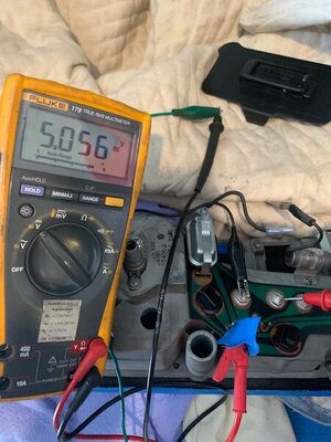
1) Have 5.06 volts at tank
2) When I ground 5vt wire the needle goes to full
3) Pulled fuel tank, pulled float, float reads 14 ohms on full and 75 at empty
4) Connected the float into wiring harness at vent panel and moved the float. At empty the needle sits all the way at the bottom. Moving the float up to full it only reaches the halfway point on gauge and stops
5) Seems to be questions about Rally gauge vs Cluster, is there more of a difference than just looks ?
6) Thing gauge is bad but...
7) Think adding a resistor would make it worse
8) added pics because we all like them, hope this works
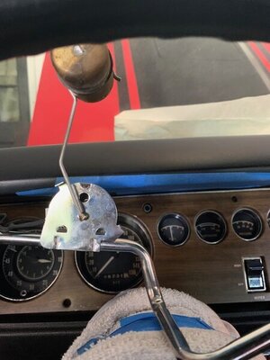
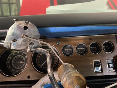
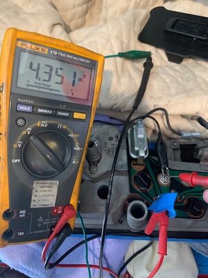
fuel full.jpg fuel empty.jpg Fish.jpg
 
If your temp gauge got smoked it probably ruined your fuel gauge as well. They are both run through the volt limiter on the circuit board. There is a sensitive spring that operates the needle and heat will alter the specs of the spring.

If you can pull the gauge, you can test it with a tester and proper voltage.
 
Drat // gas tank back in and dash board back out.
Thanks
 
Did you try a solid ground at the tank/sender end?
 
Installed dedicated 14 stranded wire between frame and fuel float plate at tank. Dash also has ground strap from body to instrument panel. ??
 
When I open the dash back up I am thinking to replace all three gauges oil, temp and fuel, also want to replace clock with tac, Am I foolish not to replace circuit board ? It is in good shape. Just finished going through the under dash harness, cleaning connections and fixing things. Was surprised at how good of shape it was in.
 
Fuel Gauge Guru's

Fuel gauge still not work

New Gauge and sending unit installed, wire's metered and ohmed , we grounded the grounds front and back
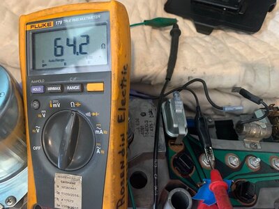
All other gauges seem to be working. Getting 64 ohms off tank, when the gauge is grounded it sweeps as it should, 5 volts on circuit board
Removed dash (4th time)
1) Checked circuit board looks good, meters out as good
2) Temp power (12 volts ) and grounds to cluster. Connected wire from tank directly to gauge, bypassing circuit board, still nothing
3) Needle swings cleanly , have wiring diagram, the only thing that's not new is circuit board
Want to understand the problem instead of just replacing parts.
4) 1970 GTX with cluster
Any thoughts or comments appreciated
Thanks Lyle

pic 1.jpg pic2.jpg pic 3.jpg
 
Brand new gauge bad ?
If I get the gauge to sweep it should be good ???
Pulling gas gauge out of cluster and wiring it independently
5 volts , ground , tank wire
What could go wrong, will report back
 
Brand new gauge bad ?
If I get the gauge to sweep it should be good ???
Pulling gas gauge out of cluster and wiring it independently
5 volts , ground , tank wire
What could go wrong, will report back

Going to ask the obvious....have you replaced the thermal-mechanical OEM instrument panel voltage regulator? With the electronic type being offered by RTEngineering? As long as you've gone to all this effort and expense.....why not. The electronic device offers protection for the instruments incase of sending unit failure. Just my opinion of course...
BOB RENTON
www.rt-eng.com/index.php/RTE_limiter.html
 
Last edited:
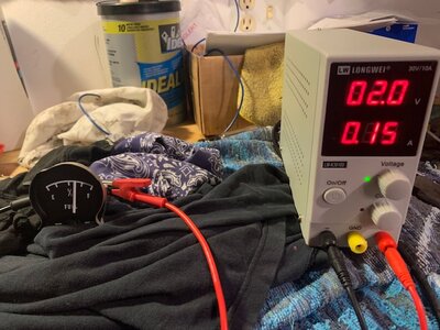
1) Tested gas gauge, seems to work fine, goes up and down as I change the voltage
2) Rather new voltage regulator. 5 volt output.
And thinking to replace the circuit board while I'm here but don't think that is the problem

2.0.jpg VR.jpg
 
1) Tested gas gauge, seems to work fine, goes up and down as I change the voltage
2) Rather new voltage regulator. 5 volt output.
And thinking to replace the circuit board while I'm here but don't think that is the problem

View attachment 1258851 View attachment 1258853
The RT_Engineering voltage regulator was just a suggestion....it appears that you have already replaced it with the www.ChargerSpecialties.com unit....very similar. Change the circuit board????....its up to you....can't hurt....
BOB RENTON
 
Going to ask the obvious....have you replaced the thermal-mechanical OEM instrument panel voltage regulator? With the electronic type being offered by RTEngineering? As long as you've gone to all this effort and expense.....why not. The electronic device offers protection for the instruments incase of sending unit failure. Just my opinion of course...
BOB RENTON
www.rt-eng.com/index.php/RTE_limiter.html
Seconded.
 
Will wire the gauge directly to the tank tomorrow and work my way out, will update
 
Pulled sending unit and wired directly to gauge
Sending unit runs from 75 ohms (empty) to 11 ohms (full)
Gauge unit runs from 66 ohms (empty) to 11 ohms (7/8)
Don't get to E mark on the gauge until I get 66 ohms
So, do I look for a different Sending unit? I need to lower the resistance, adding a resistor will not fix the problem, am I looking at this correctly ?

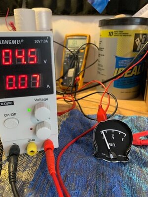
40 ohms eighth.jpg
 
Appears your bench power supply voltage is set a tad low, needs to be at 5-5.5 volts. Sender resistance readings appear nominal per spec.


C-3826.jpg
 
Was wondering about that. Didn't want to toast my new gauge. Will run up to 5 volts and update
 
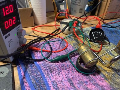
Next, I would bring the aftermarket voltage limiter into play on your bench testing. Supply 12-13 volts from the bench power supply to the limiter, then from the limiter to the gauge. Voltage limiter could be failing to maintain the 5 volts while under load.

Just noticed you believe your temp gauge is “toasted”. Has it been removed from the circuit board? If temp gauge is shorted, it cold mess with the voltage limiter function while these components are connected in the circuit board and under load.
 
Last edited:
Installed voltage limiter in test circuit, works perfect at 5 volts. All other gauges are working properly. After cycling float with gauge hooked up many times, can see how gauge lags the float level and seems to be more inaccurate below half tank. Thinking the float is not matched to the gauge or just not working properly.
Pic is at 60 ohms at empty mark

60 ohms at empty mark.jpg
 
I would now assemble the gauge and limiter into the cluster frame, make your connections at the circuit board pins, bench test once more prior to installing the cluster back into the car. Reproduction sender? Not uncommon to have to verify the same full sweep range on the sender out of the tank, corresponds to the float locations in the tank. Requires visual inspection, likely some bending adjustments are required.
 
Yep have a new sending unit coming and will put it back together in stages, but still need to get gauge and sending unit to match. Nothing worse than a inaccurate gas gauge
 
Auto Transport Service
Back
Top