• When you click on links to various merchants on this site and make a purchase, this can result in this site earning a commission. Affiliate programs and affiliations include, but are not limited to, the eBay Partner Network.

Gauge Issues

Actionjackson

Member
Local time
4:46 PM
Joined
Dec 12, 2016
Messages
10
Reaction score
2
Location
Franklinville NC
any help would be appreciated. Just completely re wired my 70 Roadrunner. Used American Autowire classic update harness. The harness only supports voltage and not the ammeter gauge that was original. Also had to install a single wire self regulating alternator. Gutted a voltage gauge and planted the face from the OER alternator gauge and put back in original spot in cluster and used nylon washers so the gauge wouldn't ground to cluster housing. Everything works great but the temp and oil pressure gauge. They peg even when disconnected from the senders. They are replacements that worked before the re wire. Any suggestions. Thanks
 
any help would be appreciated. Just completely re wired my 70 Roadrunner. Used American Autowire classic update harness. The harness only supports voltage and not the ammeter gauge that was original. Also had to install a single wire self regulating alternator. Gutted a voltage gauge and planted the face from the OER alternator gauge and put back in original spot in cluster and used nylon washers so the gauge wouldn't ground to cluster housing. Everything works great but the temp and oil pressure gauge. They peg even when disconnected from the senders. They are replacements that worked before the re wire. Any suggestions. Thanks

Hmm, if they are pegging while not hooked up to the senders, I would guess the signal must be coming from the cluster board. You might try to shrink wrap or electrical tape the screws/posts where they penetrate the board to be sure they are not touching the contacts.
 
Ah, nevermind I see that you only had to isolate the voltage meter and are still using the board for the ones that aren't working so that isn't it.
 
IMG_1499.JPG
 
I have been looking over the wiring diagram and can't yet see how the voltage meter swap would affect the cluster since they are separate circuits. I am still looking, will let you know if I find anything that could cause this.
 
There is a dark blue trace (striped) wire that normally goes from the alternator to the pin 7 on the gauge cluster connector. What happens with this wire on the 1 wire alternator? It must be something with this wire I think.
 
Looks like the (+) field terminal (edited minus to plus, oops) from the alternator normally goes to pin 7 on the cluster board connector. Did the 1 wire alternator have any provision for this?
 
Last edited:
Is there even a round cluster board connector there? The wiring diagram shows it (like my 72) but i don't see it in the photo. :realcrazy:
 
The only wire that leaves the alternator goes through the ballast resistor to the starter solenoid. don't know if this helps but I did have to eliminate the voltage regulator because the new alternator is internally regulated.
 
Sorry. After reviewing the instructions the wire I spoke of earlier goes through ballast resistor to coil. Wire goes straight from alternator to starter solenoid.
 
image.jpg
image.jpg
Well guys I may have found the culprit. A rep with American Autowire saw my post here and emailed me and said they found an error in their instructions for my application and sent me the correct diagram. Above are pics of the correct and incorrect connections. The one on top is the incorrect connection. I have tried the correct connections and not getting anything. Is it possible it has fried my gauges or circuit board or both.
 
View attachment 379071 View attachment 379070 Well guys I may have found the culprit. A rep with American Autowire saw my post here and emailed me and said they found an error in their instructions for my application and sent me the correct diagram. Above are pics of the correct and incorrect connections. The one on top is the incorrect connection. I have tried the correct connections and not getting anything. Is it possible it has fried my gauges or circuit board or both.

It wouldn't fry the circuit board, and if it did, you would see it. I suppose it could have killed the gauges. If you can find the voltage range the sending unit provides, you could bench test them with a battery/batteries.
 
If I'm right u should have 5v(from voltage limited)going to each gauge & the sender varies the other side from a "good" ground to a "kinda" ground thru resistance in the sensor.
 
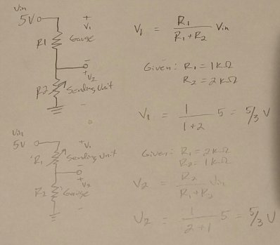
Yes, though it doesn't matter if the sending unit is between supply and gauge, or gauge and ground. I don't know which way they did it. I did a little example with made up values.

IMG_20161215_131838-1.jpg
 
Auto Transport Service
Back
Top