• When you click on links to various merchants on this site and make a purchase, this can result in this site earning a commission. Affiliate programs and affiliations include, but are not limited to, the eBay Partner Network.

Instrument panel voltage regulator

RobP

Well-Known Member
Local time
10:43 PM
Joined
May 27, 2016
Messages
256
Reaction score
379
Location
MA
What started as "I think I'll replace my instrument cluster lights with LED's" last fall turned into a full gauge cluster restoration. I've had a heck of a time getting all of the lights/blinkers/dimmer working now that it's back but I've since managed to fix those issues. Now my fuel, oil temp and temp gauges aren't working (the fuel gauge was working at first) I think it's related to the voltage regulator.
68_behind_dash3.jpg


Can anyone tell me where this wire goes in the picture? It looks like it goes to one of the 3 connections on the voltage regulator, but mine pulled out while I was installing the cluster.
Any idea?
 
Looks like you are referring to the capacitor next to the voltage limiter. It goes to the +12v input terminal on the limiter. Its function is for "noise suppression" or in simpler terms, its a DC voltage filter. Smooths out the +12V dc power to the voltage limiter.
 
Invest in an electronic limiter. You'll be glad you did.

As part of my cluster restoration, I had them include a solid state voltage limiter (same thing?). Since the fuel, oil pressure and temp gauges aren't working, I wonder if it's the new limiter? I ordered a new one today to check.
 
Last edited:
Looks like you are referring to the capacitor next to the voltage limiter. It goes to the +12v input terminal on the limiter. Its function is for "noise suppression" or in simpler terms, its a DC voltage filter. Smooths out the +12V dc power to the voltage limiter.
Thanks, I didn't know what it was.
Since the wire would only reach the middle post (I think that's the 12v input but I'm not 100% certain), I attached it there but those 3 gauges still don't work. I ordered a new limiter today.
 
What started as "I think I'll replace my instrument cluster lights with LED's" last fall turned into a full gauge cluster restoration. I've had a heck of a time getting all of the lights/blinkers/dimmer working now that it's back but I've since managed to fix those issues. Now my fuel, oil temp and temp gauges aren't working (the fuel gauge was working at first) I think it's related to the voltage regulator. View attachment 401895

Can anyone tell me where this wire goes in the picture? It looks like it goes to one of the 3 connections on the voltage regulator, but mine pulled out while I was installing the cluster.
Any idea?

Just to clarify how the limiter works here's the scoop. When your ignition is on, voltage goes to one terminal of the limiter. Inside is a bimetal that heats and cools at a certain rate causing a contact to open and close (pulses). The 12 volts supplied is reduced by heating the internal bimetal and there is only 5 to 7 volts that are allowed to pass through to the out feed terminal. This left over 5 volts powers through the guages to the various sending units and then to ground via resistance of the fuel level sensor, temp sensor etc. Most times the sending units are matched by resistance to the gauges coils that move the needles. If there is a variance in the voltage supplied by the limiter, say to low, the gauges read lower than actual and vice versa for over voltage ( usually the gauge coils fry ). If there's a dead short to the senders, the needles go to peak because there is no variances in resistance that's normally created by the senders. Get an electrical diagram, note the color codes for the various senders and make sure they are wired accordingly or you may end up with a bunch of pooched gauges. If it goes through a circuit board follow the tracers to the respective pins. Perhaps your gauge cluster is not wired properly to integrate the electronic limiter or your gauges will not work with an electronic limiter because they need the pulses created by the original limiter. And above all take note that the limiter itself is grounded via it's mounting screw.
 
And above all take note that the limiter itself is grounded via it's mounting screw.

My limiter's 3 tabs were just pushed into the cluster, I didn't see a mounting screw (?) I was able to just pull it out and then press it back in. What am I missing?

Great info Yatzee! Thanks.
 
On your car one of the tabs that is inserted into the cluster IS the ground. Other years are grounded with a screw as Yatzee said, just not yours. One is +12 vdc input, one is "ground", and one is the +5 vdc output to the gauges.

Also, the pulsed voltage to the gauges that he mentioned is still +12V pulses, but due to the duty cycle involved, it ends up being around +5V dc "average" voltage. I know, more info than you want or needed.
 
That all there is to it. To the best of my knowledge.
Same as my 66 Satellite. When the bimetal are having problems You'll here bink periodically, as the bimetal separates and your gauges will bounce. If you don't know what it is it will drive you nuts.
 
The limiter is fine (I tested it)
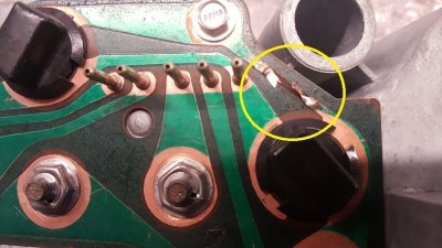
Here's the problem. This is the ground circuit that goes into the top prong of the limiter. Can this be repaired? I know I can get a new board, but I'd much prefer to repair it if possible.

2017-03-07 08.27.41.jpg
 
It would be delicate solder job. I'd remove the screw and light bulb and put an eye end on a piece of 22 gauge wire and put it under bolt. Then solder the wire to the circuit board. You really have nothing to lose trying this, maybe wait for other ideas. Why did burn out?
Volt limiter stuck closed, don't think that would burn it but I can't say. I'd keep an eye open for a replacement.
 
Just solder a short piece of wire across the break in the circuit trace. Clean the copper on both sides first, then solder the wire to the trace. That green stuff is an insulator, needs to be cleaned off to copper only. Easy fix, not that delicate of a job, at least for an Electronic Tech.
 
Fixed! Thanks for the info!!
 
The limiter is fine (I tested it)
Here's the problem. This is the ground circuit that goes into the top prong of the limiter. Can this be repaired? I know I can get a new board, but I'd much prefer to repair it if possible.

View attachment 402421

Very helpful thread! I found the exact same problem on my board (same exact trace) as well and now feel like I have a decent chance at repairing it.

Thanks, everyone.
 
Auto Transport Service
Back
Top