• When you click on links to various merchants on this site and make a purchase, this can result in this site earning a commission. Affiliate programs and affiliations include, but are not limited to, the eBay Partner Network.

Looking for Gauge Cluster Voltage Regulator - 1973 Charger SE

Strykr73

Member
Local time
4:25 PM
Joined
Jul 31, 2022
Messages
22
Reaction score
11
Location
Pennsylvania
I have reasons to suspect that the 6V voltage regulator in my '73 Charger is bad. The symptoms being: A) No responsiveness from Oil Pressure, Fuel Level, or Temperature gauges. B) DC Voltmeter measures never sees 12V, and always less than 6V on average while measuring output.

Here is a picture of the regulator:
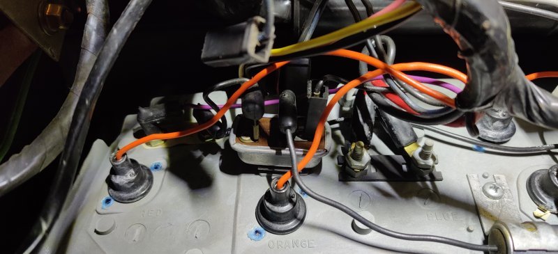
IMG_20220820_175543.jpg
It has three terminals on the rear. I don't remember the order. It also has a clip on the front which is folded over and screwed to the back of the cluster.

I purchased a regulator which claims to be correct for this model and year but it isn't. You would think by this point I would have learned to take things apart first before buying the replacements...

I've seen some examples of where people have purchased off-the-shelf linear regulators and put them in place here, but I'm not convinced that's the best way to go, considering it's nearly impossible to get this stupid dashboard out.

Advice welcome and appreciated!
 
If you cannot locate one that is identical, look at similar year Ford applications, I believe they used them as well.
 
It is called a voltage limiter and Real Time makes a new digital unit that is more reliable than the old ones for around 70.00
I've used several. Just install one in a 70 GTX last week.
There are two styles. The 71-4B 70-4 E unit that you have. The other has 3 blades that plugs into the circuit board.
Also they send a 12V pulse to the temp, fuel and oil gauges. Not to the amp gauge. Grounding the sending unit wire will peg out the gauge is the limiter is working.
 
Thanks, moparmarks! I went ahead and ordered one from the site you linked. I'll update this thread once I get it installed.
 
It is called a voltage limiter and Real Time makes a new digital unit that is more reliable than the old ones for around 70.00
I've used several. Just install one in a 70 GTX last week.
There are two styles. The 71-4B 70-4 E unit that you have. The other has 3 blades that plugs into the circuit board.
Also they send a 12V pulse to the temp, fuel and oil gauges. Not to the amp gauge. Grounding the sending unit wire will peg out the gauge is the limiter is working.
[/URL]
Just to add to this a little, the real time one outputs 5 volts to the gauges which good. They also have a little red LED light on them so you can tell it's working (you'd have to look under dash to see it). Also, you won't need the capacitor you have there.
 
Maybe you got the VL for the standard cluster while you needed for rallye cluster. Sure the seller didn't know that difference.

Several other Mopars got the same one but just a diff bracket shape.

The difference between them is not actually because is standard or rallye cluster per se, but those using a PCB or not. So we have for example 2nd gens ( both rallye and standard ) using the one which on 3rd gens also used JUST on standard cluster, just because both cluster on 2nd gens used a PCB.
Well said. This is what it looks like on a 3rd gen standard cluster. It "plugs in" to the PCB. Note the "paper" under the middle prong and where the capacitor wire plugs in together with the middle prong. Looks like rallye mounts differently and wires plug into it.

thumbnail_IMG_2092.jpg


thumbnail_IMG_2093.jpg
 
Pretty much everything except 71-4B Rallye and E body uses the 3-blade shown above including 72-80 trucks. A body Rallye and 66-7 Charger have them built into one of the gauges. All other 66-70 B and 67-76 A non-Rallye use the 3-blade.
 
The paper is an isolation between the positive output from the VL chassis preventing an accidental short
 
Just to add to this a little, the real time one outputs 5 volts to the gauges which good. They also have a little red LED light on them so you can tell it's working (you'd have to look under dash to see it). Also, you won't need the capacitor you have there.
Update: I got the new limiter installed today, but it didn't solve the problem. Still the gauges refuse to work, and I am not getting a clean output.

I can see on the limiter that the red LED on it is blinking on and off. If I put my DMM on it, I see the voltage bounce around between 0 and ~2V DC (depending on the terminal). I'm not seeing 12V on the input side, which is weird, though this could be due to the internal circuitry or some sort of shunt. Any ideas why this might be happening?

You say I can remove the capacitor. By that do you mean the round, silver thing also connected to the ignition terminal on the right? (Middle connection) Could that be the problem?
In regards to the physical nature of the regulator, I can confirm that this new one I received is the correct fit. As you can see in the pictures I included earlier, I do not have a PCB cluster. Everything is wires and plugs and terminals and screws.

As far as I know, the limiter is okay, but there is definitely something else screwing up the circuit and causing it to not work properly.


P.S. Does anyone know how to get this damn dashboard out? It would be infinitely easier for me to troubleshoot on the workbench rather than having to contort myself under the dash and seat all the time. I can't find what is holding this thing together. I also need to pull the radiator core, so taking the entire dash out would be acceptable and preferable.
 
==Another Update==
After fiddling around some more and doing more troubleshooting, I've figured out that the gauges are functional, and the issue is most likely open circuits/broken wires.

I started Another Thread regarding the oil pressure sending unit. I did get it working after posting that thread, but I still am hesitant to believe that I have it optimally wired. If any of you have any personal experience with that, I welcome it.

So for now the temperature sending unit and fuel level sending unit are still not working. Here are the results of my troubleshooting:

===Temperature Sending Unit===
- Responds to changes in temperature by lowering its own resistance.
- Lowest resistance measured was roughly 27 Ohms. Average resistance at running temp was about 32-37 Ohms
- Voltage measured by DMM at wire for sending unit (disconnected) was 0 Volts. No fluctuations.
- Wire for sending unit did not have a short to ground. Resistance from wire to ground was infinite.
===Temperature Gauge===
- Used a 100 Ohm resistor to tie the input to ground. I saw the gauge increase, and then removed the resistor and it went back to 0.

===Fuel Level Sending Unit===
- Voltage measured by DMM at wire for sending unit (disconnected) was 0 Volts. No fluctuations.
- Wire for sending unit did not have a short to ground. Resistance from wire to ground was infinite.
- I do not see a separate ground wire on the sending unit, so I'm going to assume that it's good.
(I forgot to measure the resistance to see if the wire was grounded out somewhere.)
===Fuel Gauge===
- Tried using the same 100 Ohm resistor trick (removed the blue wire and rand the input terminal to ground), but there was 0 movement on the gauge. Is it possible I have a bad gauge? Or am I testing it incorrectly?
 
Update: I got the new limiter installed today, but it didn't solve the problem. Still the gauges refuse to work, and I am not getting a clean output.

I can see on the limiter that the red LED on it is blinking on and off. If I put my DMM on it, I see the voltage bounce around between 0 and ~2V DC (depending on the terminal). I'm not seeing 12V on the input side, which is weird, though this could be due to the internal circuitry or some sort of shunt. Any ideas why this might be happening?

You say I can remove the capacitor. By that do you mean the round, silver thing also connected to the ignition terminal on the right? (Middle connection) Could that be the problem?
In regards to the physical nature of the regulator, I can confirm that this new one I received is the correct fit. As you can see in the pictures I included earlier, I do not have a PCB cluster. Everything is wires and plugs and terminals and screws.

As far as I know, the limiter is okay, but there is definitely something else screwing up the circuit and causing it to not work properly.


P.S. Does anyone know how to get this damn dashboard out? It would be infinitely easier for me to troubleshoot on the workbench rather than having to contort myself under the dash and seat all the time. I can't find what is holding this thing together. I also need to pull the radiator core, so taking the entire dash out would be acceptable and preferable.
Instructions on mine (standard cluster) said to remove the capacitor. Not sure if that's the problem. Not seeing 2V on the input side seems like the issue.
 
Have you checked gauges are in working order really? Can be tested with any DC voltage source between 3-5 volts at the studs. The needle will move
 
Have you checked gauges are in working order really? Can be tested with any DC voltage source between 3-5 volts at the studs. The needle will move
So I did list the tests I did in my last post. The only gauge that doesn't seem to be working is the fuel gauge. The issue seems to primarily be bad wires/open circuits. Both the oil pressure and temp gauges will move, and the oil pressure is actually working now. The fuel gauge will not budge.

I do have a variable DC power supply which I could connect to the fuel gauge to see if it works then, but my previous test of grounding out the sending unit input did not move the gauge at all. Also I'm reasonably confident it isn't wired backwards, although it's hard to say if it is getting a good source through the connection feeding it (there is no circuit board, solder joints, or eyelets. The connections are hollow rubber boots with a cylindrical contact inside - like a spark plug wire).
 
Auto Transport Service
Back
Top