You are using an out of date browser. It may not display this or other websites correctly.
You should upgrade or use an alternative browser.
You should upgrade or use an alternative browser.
68-70 B-body factory a/c vacuum line routing
- Thread starter Richard Cranium
- Start date
Floor heat is controlled by two small doors on the bottom of the unit that are manually opened and closed. Small wheels stamped floor heat.
My manual does not show them. They are just above the front of the console.
From what I have found they will not heat the passenger compartment on their own.
So in other words, when you put it on heat, it should still blow out the dash vents? If so, then I guess I'm good.
mopar 3 B
Well-Known Member
Thats what mine has always done. For the size of the floor vent they are verly foot warmers.

JimKueneman
Well-Known Member
So in other words, when you put it on heat, it should still blow out the dash vents? If so, then I guess I'm good.
Yea forget everything you think you know about AC systems. This one does not work anything like a modern heater/AC setup
JimKueneman
Well-Known Member
I would really like to know how yours work when done. Today I believe I understand the whys and hows of this system works. I had my core redone by Glenray and he can't get the correct thickness core anymore so it is thicker (more capacity). Now when I have the AC going and I try to blend in some warm air it is like I shut the AC off. The heater core "h" valve is in and functional. I believe its job is to basically shut off half the heater core when the AC is on for this reason so the heater does not over power the condenser when trying to blend in a little warmer air. I think Bob's cores are just too much core to make the AC/Heater system work correctly anymore. I have been thinking about putting a restrictor in choke off the flow to the heater core to try to compensate but I have not got to that yet.
thatgreatday
Member
Last question;
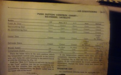
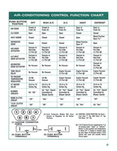
Is this the correct orientation as viewed on the drawing with #1 being the bottom left on the row of three & #7 being on the top left?
View attachment 497108
Hi Richard, I had a tricky question about figure 1 (attachment 497108) vacuum line routing that I'm also working through on my 68' Coronet. Vacuum lines 3,4 and 7 are white/black, while lines 1,2 and 5 are red/black. Line 6 is the primary vacuum line connected to manifold vacuum which I'll state here in case it helps anyone. It's my understanding that the "red lines go to the rod side" of the actuator as the rule of thumb and that the white/black lines go to the "pot" side or the top of the actuators. It's also my understanding that the white lines open the actuators, the red lines close the actuators. My issue is with figure 1 which you kindly uploaded. In the diagram, just using the fresh air door actuator as an example (lines 1 and 3), if I follow the "red to rod side rule" (not the diagram, but the rule), the red line #1 would go to the rod side and line # 3, the white line would go to the pot side (top). But if I follow the diagram, it would be reversed because the diagram, the way I see it, is showing the red line 1 going to the top/pot side and the white line going under to the rod side. Do you see that?
That was 2 months ago & I can't remember that far back. Hopefully a/c guro Mopar 3-B will chime in.
mopar 3 B
Well-Known Member
The heater should flow just enough to keep the condenser defrosted. Is your h valve hooked up? Not sure what you have it will be actuated by cable or vacuum.I would really like to know how yours work when done. Today I believe I understand the whys and hows of this system works. I had my core redone by Glenray and he can't get the correct thickness core anymore so it is thicker (more capacity). Now when I have the AC going and I try to blend in some warm air it is like I shut the AC off. The heater core "h" valve is in and functional. I believe its job is to basically shut off half the heater core when the AC is on for this reason so the heater does not over power the condenser when trying to blend in a little warmer air. I think Bob's cores are just too much core to make the AC/Heater system work correctly anymore. I have been thinking about putting a restrictor in choke off the flow to the heater core to try to compensate but I have not got to that yet.
mopar 3 B
Well-Known Member
If I am corret the Cornet used the same dash and heater box as the Charger.Hi Richard, I had a tricky question about figure 1 (attachment 497108) vacuum line routing that I'm also working through on my 68' Coronet. Vacuum lines 3,4 and 7 are white/black, while lines 1,2 and 5 are red/black. Line 6 is the primary vacuum line connected to manifold vacuum which I'll state here in case it helps anyone. It's my understanding that the "red lines go to the rod side" of the actuator as the rule of thumb and that the white/black lines go to the "pot" side or the top of the actuators. It's also my understanding that the white lines open the actuators, the red lines close the actuators. My issue is with figure 1 which you kindly uploaded. In the diagram, just using the fresh air door actuator as an example (lines 1 and 3), if I follow the "red to rod side rule" (not the diagram, but the rule), the red line #1 would go to the rod side and line # 3, the white line would go to the pot side (top). But if I follow the diagram, it would be reversed because the diagram, the way I see it, is showing the red line 1 going to the top/pot side and the white line going under to the rod side. Do you see that?
I have never depended on hose color whole placeing lines. Actually never gave it much thought as the ports are numbered on the factory diagrams and have always either pressure or vacuum tested the lines one at a time for proper placement.
See post 6 figure 46. It labels the function of each port.
But your observation is interesting and will look into it.
JimKueneman
Well-Known Member
The heater should flow just enough to keep the condenser defrosted. Is your h valve hooked up? Not sure what you have it will be actuated by cable or vacuum.
NOS h valve that is actuated by a mechanical arm connected to the lower door. I can feel it is shutting off half the core when in AC mode.
thatgreatday
Member
If I am corret the Cornet used the same dash and heater box as the Charger.
I have never depended on hose color whole placeing lines. Actually never gave it much thought as the ports are numbered on the factory diagrams and have always either pressure or vacuum tested the lines one at a time for proper placement.
See post 6 figure 46. It labels the function of each port.
But your observation is interesting and will look into it.
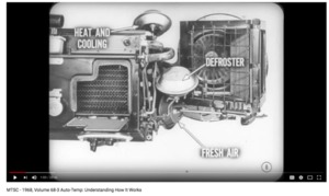
Thanks Mopar 3B and Jim for replies. I've checked the wiring harness from the controls and all is perfect. My vacuum tube assembly is numbered correctly (see photo), but I am still struggling to understand which decision to make. It has to be one or the other. If I follow the diagram ( see post #7 and again in post #10), some of the white lined tubes will be on top of the pot and some on the rod side. But if I follow the red side to rod side then it won't follow the diagram. I have tried both and neither are working the buttons correctly that I can tell. Either way, when I press off, the door closes and the heat comes on, when I press Defrost, the fresh air door closes, the fan shuts off (which is the correct reaction for off.) My A/C compressor is not hooked up as it is totally blown up. I'm taking wild guess that maybe the clutch and compressor need to be hooked up in order to complete the vacuum circuit--but that is a wild guess in the dark. That particular red to rod side info came from this video
.
Basically I said to myself, before I spend a bunch of money on the new A/C compressor and clutch, let's make sure the vacuum actuators all work and the doors close and open etc. Well, they do, but not in in order which makes sense with the buttons!! Oh my! Bombing us with some photos in case this thread helps me or someone else! Thanks gentlemen! Not all of this is perfectly related to my 68' Coronet 440 but I'm thinking it's likely very relevant.
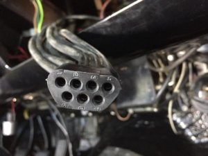
Last edited:
JimKueneman
Well-Known Member
See if my thread helps you at all here:
http://www.forbbodiesonly.com/mopar...net-500-project.114333/page-22#post-910578933
http://www.forbbodiesonly.com/mopar...net-500-project.114333/page-22#post-910578933
mopar 3 B
Well-Known Member
Compressor or clutch missing from the system has no affect on door functions. Just do not expect cold air in ac mode.
thatgreatday
Member
Thanks Mopar3B. That would make sense to me so it's nice to get the confirmation.Compressor or clutch missing from the system has no affect on door functions. Just do not expect cold air in ac mode.
thatgreatday
Member
Amazing thread, thanks tons! Everything I can see in all those awesome photos confirms the "red to rod side" theory supported in the video and "white to 'pot'/top side". The white is opening the system and the red is closing the system if I'm understanding what I've discovered.See if my thread helps you at all here:
http://www.forbbodiesonly.com/mopar...net-500-project.114333/page-22#post-910578933
thatgreatday
Member
Also, incase anyone chases down this link months or years from now, here's a good point for available reference materials http://www.mymopar.com/index.php?pid=446
monroegtx
Well-Known Member
Thanks for the link. Gradually putting the factory a/c back in my gtx and its good to have all these links. I was a bit confused with the colour hoses as well. Didn’t seem to match up with my diagram.Also, incase anyone chases down this link months or years from now, here's a good point for available reference materials http://www.mymopar.com/index.php?pid=446
thatgreatday
Member
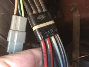
Monroegtx, I believe I owe you a huge thanks! I ended up looking through your photos in your "garage". I was saying previously that all my switches at the back of the a/c heat control panel are wired correctly. I had been saying that I believe that all my vacuum lines are correctly connected to the actuators for the A/C heat doors. But I had been saying that the buttons just don't do what they are supposed to do. I took a long hard look back at the wiring diagram in my book AND at the pictures of your heating and a/c controls which you posted. I couldn't figure out how you were ending up with the blue wire for A/C on top until I stared and stared and stared at your photo and then looked at mine. Then the epiphany hit me. The previous owner had installed the heater a/c vacuum switch upside down! So all the buttons were not aligning with the correct valve actions. It's not even 6:30am here in California so I can't start her up quite yet but I flipped that heater a/c switch over! I'll keep you all posted. Thanks tons. Picture 1 correct from MonroeGTX, picture 2 NOT correct (my set up how it was), picture 3 corrected to match picture 1.Thanks for the link. Gradually putting the factory a/c back in my gtx and its good to have all these links. I was a bit confused with the colour hoses as well. Didn’t seem to match up with my diagram.
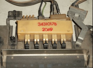
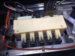
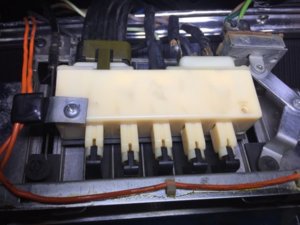
Last edited:
themechanic
Oklahoma is OK
- Local time
- 1:47 AM
- Joined
- Nov 11, 2012
- Messages
- 19,039
- Reaction score
- 23,981
- Location
- Moore, Oklahoma
Now I understand why most people chunk those outdated systems for Vintage Air or Classic Air. Sheesh!
My hat is off to you gentlemen for keeping it original and in good working nick.
My hat is off to you gentlemen for keeping it original and in good working nick.
Similar threads
- Replies
- 16
- Views
- 1K
- Replies
- 29
- Views
- 2K

