• When you click on links to various merchants on this site and make a purchase, this can result in this site earning a commission. Affiliate programs and affiliations include, but are not limited to, the eBay Partner Network.

69 coronet engine harness

David butler

Active Member
Local time
1:24 PM
Joined
Jan 11, 2017
Messages
27
Reaction score
0
Location
Florence, al
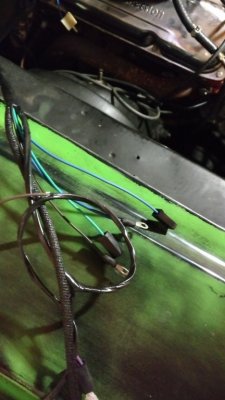
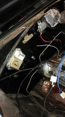
I purchased a 69 coronet a few months back. I am familiar with cars but mostly Chevy so the Dodge has presented a learning curve. When I purchased the car the guy had lost the key so I was having to crank it at the starter relay with a screw driver. I installed a new switch and cylinder and nothing when I turned the key. I then got to messing with the wiring under the hood and realized it was a mess where someone had converted the car at some point so I ordered a new replacement harness for the electronic ignition from classic industries. I have studied the wiring schematics from the original car and I am having a hard time finding where the wires go on the new harness. Some are straight forward but I'm having a hard time the wires for the resistor and other items. I have attached a picture of the parts on the firewall. Can someone send me some actual pictures of their car so I can see where the wires go. The car has a 440. Any help is appreciated.
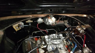
IMG_20170324_213855483.jpg
 
Which wire harness did you buy?
Was it the MB2510?
4 pin or 5 pin ECU?
Single field or dual field alternator?
If you did buy the MB2510, you bought a harness with a 4 pin ballast resistor that was used after 1969 and a dual field voltage regulator. You can still use it but you will have to modify it. The connector that looks like a triangle will have to be cut off. The green wire will go to field and the other wire to the other screw of the regulator. You don't need a 4 pin ballast resistor. The 4 pin ECU has a internal resistor.
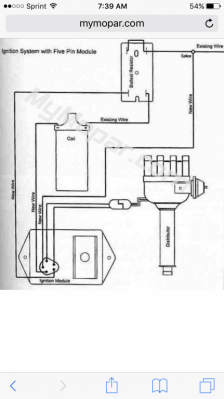
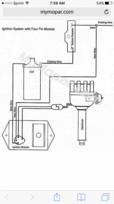
Look at the difference in the schematics below, do a simple continuity check to determine where wires start and stop. Positive coil wire to resistor connector goes to resistor.
The other connector, those wires should go to the same junction in the harness, so you should have continuity from both spots of the connector. If so, plug in either one to the resistor.

IMG_3709.PNG IMG_3710.PNG
 
Last edited:
I did purchase the mb2510 harness. The ECU is a 4 pin. When you say cut the triangle plug off and the green wire goes to field, what are you referring to as field?
My resistor is a two pole or has two plugs, not four. Which wires go to it? There is also a wire with sheilding that has a small black rubber piece on the end. Where does it go?
 
Or doni need to ship this harness abck and buy another that will plug in? If so what harness do I need?
 
Those white connectors go to your ballast resistor. It has 2 spots per connector. Read post above to plug into resistor.
The shielded wire goes to your temp sensor.
The rubber one with the male and female end in one connector will go to your distributor.
You should have a green wire with a black connector that plugs into the alternator.
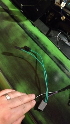
That gray connector that has 2 green wires, horn relay for the gray part and the green wires to the horns.
 
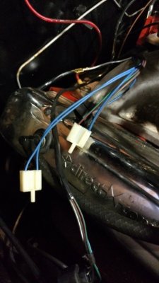
Ok do I need to do anything with the green with red stripe wire that is extra on the ECU plug? What about the black and white stripe wire that is the same length as the horn relay plug? The is a blue wire with a black plug...Does it go to the alternator too?The two coil wires, the blue on the positive and black with yellow stripe on the positive? Where does the greybwire plug that is near the firewall?
 
I still don't full understand about cutting the triangle plug off. I know one goes to the alternator, where does the other go?
 
Even with the wires not hooked to the coil, ECU or resistor should the crank not turn over and make noise with the switch...I get nothing?
 
IMG_3715.PNG
View attachment 407930 View attachment 407931
I still don't full understand about cutting the triangle plug off. I know one goes to the alternator, where does the other go?
That silver box next to the resistor is your voltage regulator. It should have a green wire and a dark blue wire going to it. You will see in the harness there is 2 wires going into a rubber boot with clips on the side and is shaped like a triangle. That is the connector for your regulator.
The other end of that green wire is the one that goes to the alternator. That extra wire up by the alternator. Tape it back for now.
The extra wire by the ECU with no connector, tape it up.
Coil wire + is dark blue other is -
 
Ok, my alternator has two pins on it. The voltage regulator that is on my car does not have the triangle plug like you mentioned in previous post. It has one pin on it. If I cut the triangle plug off like you previously mentioned does one wire go the alternator? So tape of the blue wire near the alternator and the grey wire near the firewall correct? With all of this hooked up when I turn the switch over I get nothing.
 
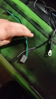
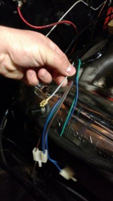
There are just a few wires I am unsure about. You have been very helpful and I appreciate it. I just need to make sure I have the grey wire( you can see me holding this wire in above picture) and blue wire (near alternator) taped up. Do I need to order a new voltage regulator? Like I said in my previous post the alternator has two pins and the stud. Does it matter which pin the green wire goes on?
 
image.jpg
If you have an alternator with 2 pins then you have choices to make.
1) connect both wires to the alternator, the green wire and the blue one I told you to tape up and buy a voltage regulator for a 1970 and up. This is a 2 field voltage regulator. This will also allow you to use the connector that came with the harness. They are of different shape and size but will work.
2) use the voltage regulator you have, cut the harness you have so you can put wire under screws of exsisting regulator, tape up blue wire and just connect the green wire to alternator. This requires the left over pin to be grounded to the case.just connect a wire to it and ground it.
That gray wire you are holding goes to your oil sending unit. May or may not be there. Located on driver side towards firewall just behind intake. It slides in to the top of the unit. Almost like there is a small pin on there.
 
IMG_3360.JPG
IMG_3361.JPG

69 70

I looked at your pic of your voltage regulator, the pin with the screw in it is where the green wire will hook to. That is your field wire. The other wire is your ignition wire, this will require a connector like the one for your alternator.
 
Last edited:
So what wire do I hook on the ignition side of the regulator? Am I better to buy a new regulator? Is the ignition wire not being hooked up keeping the car from doing anything?
 
Also can you tell me if there is something missing on the starter relay that may be keeping the car from doing anything with the switch...I can jump the two screws on the starter relay and the car will spin over. Before I could jump a wire from the resistor to the battery and it would crank by shorting out the starter relay.
 
So what wire do I hook on the ignition side of the regulator? Am I better to buy a new regulator? Is the ignition wire not being hooked up keeping the car from doing anything?
nevermind. The green wire goes under screw and blue wire will plug to the ignition side, correct?
 
Auto Transport Service
Back
Top