• When you click on links to various merchants on this site and make a purchase, this can result in this site earning a commission. Affiliate programs and affiliations include, but are not limited to, the eBay Partner Network.

Alternator output Charging system not working

TA726

Member
Local time
11:50 PM
Joined
Sep 19, 2018
Messages
21
Reaction score
37
Location
Houston, TX but home will always be in Philly
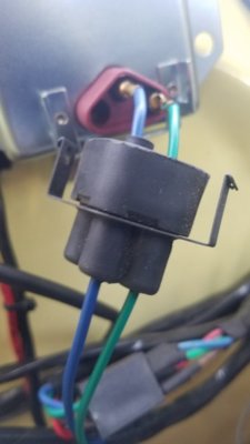
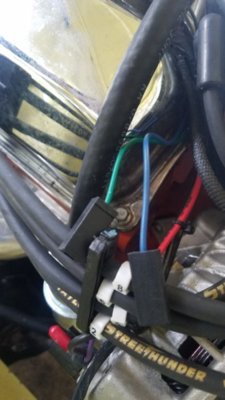
Ok fellas, I'm coming to the forum for some technical help on my charging system for this 1969 Coronet 383. I have done my research, search the threads and read through a lot of discussions already on the same topic and still have not been able to figure out why I cannot get my charging system operating. The voltage regulator on the firewall has battery voltage at the blue terminal, the green wire going from the voltage regulator to the alternator is good (I ran a jumper across to the alt anyway just to be sure). The alternator has been removed and bench tested to be putting out 13.4 volts. The voltage regulator was bought brand new and ohm tested before installation. I have ran additional grounds from both the voltage regulator and alternator just to be certain that wasn't an issue. I also went behind the gauge cluster and jumped the ammeter gauge terminals and still have not been able to get anything other than battery voltage (12.4v) coming off the main terminal of the alternator.
I can get output voltage to climb if I jump both the blue and green wire together on the voltage regulator.
I have pictures of my setup for reference. Any help would be appreciated.
Thanks in advance.
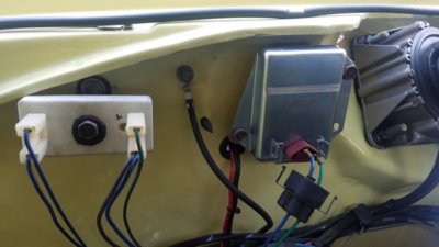
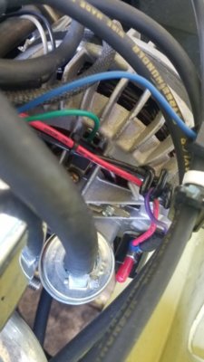
20200112_124703.jpg 20200112_124812.jpg
 
Do you have battery power to one brush holder as the voltage is controlled by a ground signal from the regulator to the other brush holder
 
Looking at your pix, it seems that you, or the previous owner, installed a 1970+ newer charging system. The 1969 models used a totally different voltage regulator and a grounded brush alternator.
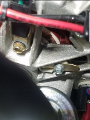
The 1970 and later designs used the voltage regulator shown and isolated field alternator. From yhe pix of the alternator, there is nothing connected to one brush....its no wonder why the unit does not charge.
In the 1970 and newer systems, the current path comes from the switched source (12 volts) to the alternators field (either brush) thru the rotating field, bsck to the other brush and back to the voltage regulator. The regulator, thru its internal circuit, grounds one wire (actually the switching transistor turns on snd off) allowing a variable voltage to flow thru the field, producing output current. The other wire at regulator (green) provides the battery reference voltage to allow the voltage regulator to know how much voltage to flow to the alternators field which in turn controls the alternators output, both voltage and current.
My suggestion....run a second wire from the unconnected brush back to the rrgulator and insure that the regulator is adequately grounded thru a separate independent wire to the engine block.
The charging system is quite simple and very reliable when correctly hooked up. PM if you want further info. If you are trying to maintain correct appearance and original appearance great. I'm sure you will be besieged by the proponents of the one wire system or to put in a Powermaster system. The choice is yours...its uour car. Just my opinion of course.
BOB RENTON
 
Thanks for the information guys. The blue wire at the voltage regulator has 12 volts on it, the green wire coming from the voltage regulator goes to 1 brush terminal on the back of the alternator while the second brush terminal has nothing connected to it. However, there is an unused blue wire (12 volts) with a connector in the area of the alternator which isn't connected to anything. Should it be? Because when I connect that blue wire to the alternator and the green to the other brush terminal, the charging system voltage spikes to 16 - 17 volts.

20200112_155455.jpg 20200112_155448.jpg
 
Thanks for the information guys. The blue wire at the voltage regulator has 12 volts on it, the green wire coming from the voltage regulator goes to 1 brush terminal on the back of the alternator while the second brush terminal has nothing connected to it. However, there is an unused blue wire (12 volts) with a connector in the area of the alternator which isn't connected to anything. Should it be? Because when I connect that blue wire to the alternator and the green to the other brush terminal, the charging system voltage spikes to 16 - 17 volts.
That charging systems uses an isolated field alternator, sounds like the terminal with the green wire on it is grounded to the alternator case. As mentioned, make sure you have the correct ’70 and up isolated field alternator. Check continuity between the terminals and the alternator case. Should not be any continuity on either to the alternator case. Check the terminal/brushes for missing insolating washers under their screw heads.
If the alternator terminals checks out, connect the blue back up, pull the green off the upper terminal. If the full field condition stops, the green wire is grounded. Disconnect the green wire from the regulator and alternator, check the wire for continuity to ground. Should not be there, if it is, it’s pinched under something.
 
Last edited:
Thanks for the information guys. The blue wire at the voltage regulator has 12 volts on it, the green wire coming from the voltage regulator goes to 1 brush terminal on the back of the alternator while the second brush terminal has nothing connected to it. However, there is an unused blue wire (12 volts) with a connector in the area of the alternator which isn't connected to anything. Should it be? Because when I connect that blue wire to the alternator and the green to the other brush terminal, the charging system voltage spikes to 16 - 17 volts.

View attachment 894208 View attachment 894209
Short answer....YES. Connect that wire to the unused terminal on the back of your alternator and it will charge just fine
 
I can connect my DVOM to the positive terminal of the battery and ground the negative side to either brush terminal behind the alternator and show 12 volts on the meter. So when I do hook up that blue wire to the back of the alternator, it initially jumps a good spark.
 
Short answer....YES. Connect that wire to the unused terminal on the back of your alternator and it will charge just fine
Should it be? Because when I connect that blue wire to the alternator and the green to the other brush terminal, the charging system voltage spikes to 16 - 17 volts.
He’s indicating that it is full fielding when both wires are connected.
 
I can connect my DVOM to the positive terminal of the battery and ground the negative side to either brush terminal behind the alternator and show 12 volts on the meter. So when I do hook up that blue wire to the back of the alternator, it initially jumps a good spark.
Sounds like the upper terminal is shorted to the case. Either the wrong alternator or that upper brush is missing an insulator.
 
Looks to me like you have a ’70 and later alternator configured for a pre ’70 car. Some alternator manufacturers/remanufacturers will ground one side like that intentionally on later cases to be used on an earlier application. Insulate the screw, you should be good.
Sometimes they will trim off the brush terminal to prevent connections there, looks like yours has been trimmed. May want to replace the brush, or get a correct ’70 and later alt.
20200112_185423.jpg
 
Last edited:
13.4 volts sounds weak to me. I've had alternators tested that were above 12 on the bench running in the 13's that were bad....not sure that the case here but alternator usually are 14.5 volt. Maybe needs going through?
 
13.5 volts or close IS THE CORRECT voltage rate. 14.5 is the max when you got a discharged batt. More and something is wrong
 
Auto Transport Service
Back
Top