• When you click on links to various merchants on this site and make a purchase, this can result in this site earning a commission. Affiliate programs and affiliations include, but are not limited to, the eBay Partner Network.

Alternator wiring update wiring diagram using higher AMP alternator

rustytoolss

Well-Known Member
Local time
9:27 PM
Joined
Mar 4, 2018
Messages
537
Reaction score
147
Location
New Franklin, Ohio
I'm replacing the low 36-42 amp alternator on my 62 Plymouth with a factory square back 78 amp unit. What updating to the wiring harness should done. I will be using a stock mopar electronic VR. Also should I continue to use the 62 factory AMP gauge ? or bypass it ? I could use a wiring diagram and wire sizes I should be using.
 
Use the search feature on here, LOTS of info on this subject.
 
Usually the alternator is not the time bomb. Over time, the firewall connectors can corrode/degrade, causing high amperage draw on this circuit. On the '62 and '63 harnesses, the wires to the ammeter actually screw to a buss bar that passes through the firewall. Periodically, unscrew these connections and clean them up, and you should never have a problem. This is a much better design than what came afterward. Nobody reproduces the '62-'63 harnesses.
 
Last edited:
Usually the alternator is not the time bomb. Over time, the firewall connectors can corrode/degrade, causing high amperage draw on this circuit. On the '62 and '63 harnesses, the wires to the ammeter actually screw to a buss bar that passes through the firewall. Periodically, unscrew these connections and clean them up, and you should never have a problem. This is a much better design than what came afterward. Nobody reproduces the '62-'63 harnesses.
and is the amp gauge still a weak point ? Or is it built better than units in newer models ?
 
Last edited:
If the circuit is properly maintained, I don't believe it is. I also upgraded to a higher output alternator, because I was adding aftermarket air conditioning. At this time, I replaced the wires in the charging circuit with 8 ga. wires. The ammeter wires were run directly through the firewall with proper rubber grommets, bypassing the factory terminal block. The ammeter is simply a gauge that shows direction of current flow. "+" means that current is flowing from the alternator to the battery (charge). " -" means that current is flowing from the battery to the alternator (discharge). I also added a volt meter to monitor the rate of charge from the alternator. I feel that the ammeter is no more dangerous than the volt meter.
 
Last edited:
I'm replacing the low 36-42 amp alternator on my 62 Plymouth with a factory square back 78 amp unit. What updating to the wiring harness should done. I will be using a stock mopar electronic VR. Also should I continue to use the 62 factory AMP gauge ? or bypass it ? I could use a wiring diagram and wire sizes I should be using.
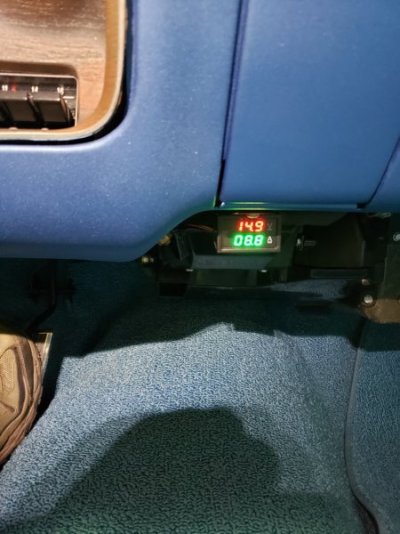
71chargerammetersensor.jpg'71chargervoltammeter.jpg I've been using my Bayite BYT-VAM-036 digital volt/hall effect ammeter for 1 year now and I have been able to get a lot of good information from it. Accuracy is +/- 1% and indicates direction of current flow so could be used in place of /in addition to factory ammeter. Nice feature is the hall effect sensor which enables you to easily place the sensor over any wire to monitor current without any splicing. Inexpensive ($25.00) unfortunately made in China. If I could locate a US made version I would buy it. Got this from E Bay. Make sure your meter includes the 6.5' sensor extension. Mine is shown at alternator output cable.
 
If the circuit is properly maintained, I don't believe it is. I also upgraded to a higher output alternator, because I was adding aftermarket air conditioning. At this time, I replaced the wires in the charging circuit with 8 ga. wires. The ammeter wires were run directly through the firewall with proper rubber grommets, bypassing the factory terminal block. The ammeter is simply a gauge that shows direction of current flow. "+" means that current is flowing from the alternator to the battery (charge). " -" means that current is flowing from the battery to the alternator (discharge). I also added a volt meter to monitor the rate of charge from the alternator. I feel that the ammeter is no more dangerous than the volt meter.
Did you add any fusible links to your wiring harness, if so where ? From what I see thier are none shown in my FSM.
 
If you are still using an original mechanical voltage regulator, there are fusible links inside it.
 
If the circuit is properly maintained, I don't believe it is. I also upgraded to a higher output alternator, because I was adding aftermarket air conditioning. At this time, I replaced the wires in the charging circuit with 8 ga. wires. The ammeter wires were run directly through the firewall with proper rubber grommets, bypassing the factory terminal block. The ammeter is simply a gauge that shows direction of current flow. "+" means that current is flowing from the alternator to the battery (charge). " -" means that current is flowing from the battery to the alternator (discharge). I also added a volt meter to monitor the rate of charge from the alternator. I feel that the ammeter is no more dangerous than the volt meter.
so if I'm reading this right...you've run larger wires / bypassed the bulkhead....and are still using the factory AMP gauge...and installed a voltmeter
 
and is the amp gauge still a weak point ?
The Ammeter - 99% of the time it only gets the blame for being a weak point because people tend to poke around under the dash while doing some unrelated modifications, and they subsequently and inadvertently move the wiring either side of the ammeter.
This movement can loosen the terminals which eventually leads to a hot spot on the connections, which on rare occasions turns into a wiring fire.

The ammeter gets the blame every time.

It is usually the fault of the person working on the car.

My best advice for anyone working under the dash is to make sure they check the ammeter terminals - make sure they are tight, and also clean. Disconnect if required, emery paper the lugs, and reconnect. Adding some di-electric grease will do no harm either.... just make sure the terminals are properly seated and tightened.
 
I'm replacing the low 36-42 amp alternator on my 62 Plymouth with a factory square back 78 amp unit. What updating to the wiring harness should done. I will be using a stock mopar electronic VR. Also should I continue to use the 62 factory AMP gauge ? or bypass it ? I could use a wiring diagram and wire sizes I should be using.

It all depends on what you're doing with the car.
Unless you're adding loads to the system (electric fuel pump/fan/water pump, more lighting, hot stereo/amp etc) then the factory wiring is fine IF it's in good shape.
Check the connections and feel the wiring to make sure it isn't stiff or brittle; that can indicate cooked or corroded wires. In most cases (if there's enough length) you can cut the bad potion off as it's usually at the end and simply re-terminate.
Remember--just because you swap in a higher output alternator doesn't mean the alternator output to the system will increase.
As for wiring diagrams, your service manual will have them..
 
My best advice for anyone working under the dash is to make sure they check the ammeter terminals - make sure they are tight, and also clean.
Yes and please folks, use two wrenches!
I've seen more ammeters fubar'd from guys tightening the top nut without holding the bottom nut than any "meltdowns"...
 
The Ammeter - 99% of the time it only gets the blame for being a weak point because people tend to poke around under the dash while doing some unrelated modifications, and they subsequently and inadvertently move the wiring either side of the ammeter.
This movement can loosen the terminals which eventually leads to a hot spot on the connections, which on rare occasions turns into a wiring fire.

The ammeter gets the blame every time.

It is usually the fault of the person working on the car.

My best advice for anyone working under the dash is to make sure they check the ammeter terminals - make sure they are tight, and also clean. Disconnect if required, emery paper the lugs, and reconnect. Adding some di-electric grease will do no harm either.... just make sure the terminals are properly seated and tightened.
(Sarcastically speaking)......I plan on arc welding, using 3/16" diameter 6010-5P red wire, maybe 7018 LH or 7024 wire, using my 200 amp alternator, engine idling at 1200 rpm as the power source ....and a ground of course, should I bypass the bulkhead wiring and amp meter or just the amp meter....will the existing wire size work or should I upgrade 1 or 2 sizes. I plan on installing a power source connection for the small TIG/MIG/stick electrode machine.....I can use flux core wire (MIG) without/with shield gas or shield gas (75-25) with TIG....or should I plan on a bigger alternator?......or.....??? Just curious.......
BOB RENTON
1729824240857.png


:lol:
 
Auto Transport Service
Back
Top