• When you click on links to various merchants on this site and make a purchase, this can result in this site earning a commission. Affiliate programs and affiliations include, but are not limited to, the eBay Partner Network.

GM HEI module - tidy up project

gottagettamopar

Well-Known Member
Local time
8:04 PM
Joined
May 30, 2013
Messages
48
Reaction score
7
Location
Thundersley,Essex,UK
I posted a thread recently to identify a gizmo attached to my dizzy and it turned out to be a GM HEI module. The advice received was to retain the module as it's considered an upgrade but I wasn't happy with the 4" chipboard screws attaching the coil to the inner fender, the offcut ally heatsink or the mounting of the module on the dizzy.
After a bit of trawling on the interweb I found a couple of neat solutions that I have adapted. I used a bit of scrap ally sheet from my local metal supplier, some careful measuring and a couple of hours cutting and filing.
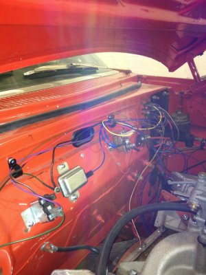
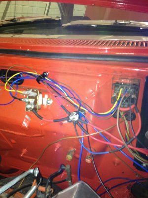
I'm rewiring everything under the hood, so hopefully this will tie in nicely and I'm adding a relay.

Make a template and figure out where the coil, module, relay and heatsink will be positioned.
IMG_0642[1].jpg

Shape up the ally sheet. I bent mine over blocks of wood held in a vice.
IMG_0646[1].jpg

Cut out a hole for the coil.
IMG_0650[1].jpg

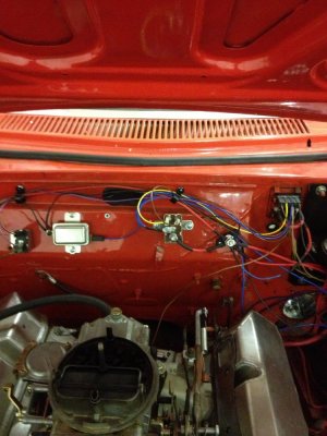
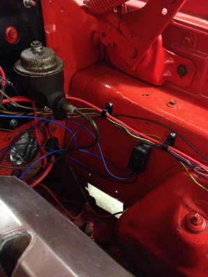
Mount the module, relay and heatsink.
IMG_0654[1].jpg

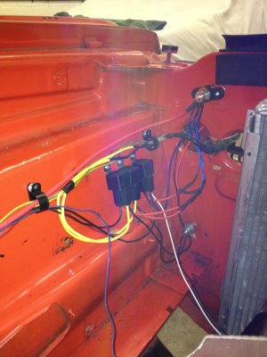
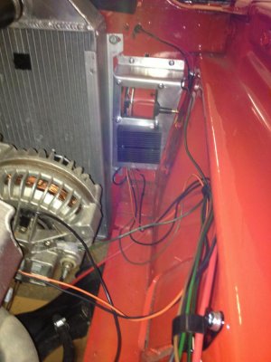
Mounted next to the radiator (sorry pic is sideways).
IMG_0656[1].jpg

I found a heatsink on fleabay. It's a used Compaq pentium unit and the contact area is perfect for the module.
I think this is quite a neat packaging solution.
 
Looks great! I used a GM HEI on my car too, but it looks like you have a relay in there too... Was that already in your wiring or did you add that yourself? What is the theory behind adding it?
 
I've only really got into relays recently but they're a great addition to older wiring, especially for upgrades like this.
I have rewired this car this week including moving the battery to the trunk, adding a remote starter solenoid, adding separate relays for low beam, high beam, electric fan and the mini starter. I've retained the original lighting harnesses and will check the under dash wiring next.
What the relays does is take it's own dedicated power supply and output that power directly to the accessory. The original wiring, in this case from the ignition switch, only supplies a very small amount of current to switch the relay. The load on the original wiring is therefore minimised and is lower than original, because the power is not running through the switch. The power supply is protected by a fuse or fusible link.
Relays on headlights make them shine like halogens!
I added a power post on the bulkhead and the radiator support which are permanent live from the battery. These power the relays and any other accessory circuits. I also added a couple of bolts that act as ground studs in similar locations. This just saves running lengths of cable all over the place and keeps everything tidy.
Attached is a diagram of how the relay wires in.
Hope this helps. I'm no expert and most of this comes from the MAD Electrical site. The ignition module wiring was on another forum.
 

Attachments

  • IMG_0664[1].jpg
    IMG_0664[1].jpg
    41.2 KB · Views: 351
I've only really got into relays recently but they're a great addition to older wiring, especially for upgrades like this.
I have rewired this car this week including moving the battery to the trunk, adding a remote starter solenoid, adding separate relays for low beam, high beam, electric fan and the mini starter. I've retained the original lighting harnesses and will check the under dash wiring next.
What the relays does is take it's own dedicated power supply and output that power directly to the accessory. The original wiring, in this case from the ignition switch, only supplies a very small amount of current to switch the relay. The load on the original wiring is therefore minimized and is lower than original, because the power is not running through the switch. The power supply is protected by a fuse or fusible link.
Relays on headlights make them shine like halogens!
I added a power post on the bulkhead and the radiator support which are permanent live from the battery. These power the relays and any other accessory circuits. I also added a couple of bolts that act as ground studs in similar locations. This just saves running lengths of cable all over the place and keeps everything tidy.
Attached is a diagram of how the relay wires in.
Hope this helps. I'm no expert and most of this comes from the MAD Electrical site. The ignition module wiring was on another forum.

Very cool. Does it really make that much difference on the headlights? I've heard/read the theory on relays, but have not yet upgraded my wiring. I may have to start :)

- - - Updated - - -

there is a company out there that has an aluminum piece that bolts under the dist housing to hold the HEI module.....

http://www.designed2drive.com/

Their mounting block looks killer too!
Dist_Side_Wires.JPG
 
The difference in the headlights is significant. The pictures below are of my Chevy on low beam and high beam without relays and of my Coronet with relays. The relays should be mounted near the accessory that they are switching. This reduces resistance in the cable run and therefore loss of power.
The original wiring provides power to the lights from the switch on the dash, which in turn is powered from a splice in the heavy gauge cable running through the ammeter from the starter relay and the alternator.
A relay in the light circuit means that the light switch only provides a very small amount of power to switch on the relay, which acts as a remote switch. The relay has it's own power supply direct from a battery positive feed and when it is switched on, it sends this power direct to the lights.
I've also attached some pictures of my wiring installation in the Coronet, yet to be wrapped.
I will post some diagrams of my wiring installation soon, so you can see how I've wired everything in.
 

Attachments

  • IMG_0667.jpg
    IMG_0667.jpg
    97.1 KB · Views: 296
  • IMG_0668.jpg
    IMG_0668.jpg
    82.7 KB · Views: 295
  • IMG_0669.jpg
    IMG_0669.jpg
    102.7 KB · Views: 289
  • IMG_0670.jpg
    IMG_0670.jpg
    96.1 KB · Views: 300
  • IMG_0672.jpg
    IMG_0672.jpg
    86.1 KB · Views: 303
  • IMG_0673.jpg
    IMG_0673.jpg
    101.1 KB · Views: 288
  • IMG_0676.jpg
    IMG_0676.jpg
    94 KB · Views: 308
  • IMG_0680.jpg
    IMG_0680.jpg
    84.9 KB · Views: 285
  • IMG_0681.jpg
    IMG_0681.jpg
    83.3 KB · Views: 289
  • IMG_0683.jpg
    IMG_0683.jpg
    102.8 KB · Views: 298
  • IMG_0684.jpg
    IMG_0684.jpg
    95.2 KB · Views: 319
  • IMG_0685.jpg
    IMG_0685.jpg
    66.9 KB · Views: 306
Attached are diagrams of the rewire I have just done as above. These show the relay for the HEI Module and the relay for the mini starter. My understanding is that the relay is required to stop the starter running on and to disengage it.
There are also additional pages for the headlights and electric fan.
Hope this helps anyone undergoing similar mods.
View attachment WIRING DIAGRAMS.zip
 
It's nice to see an updated wiring job. What are you going to use to tidy the wiring up? Electrical tape? Plastic wire loom? Just promise me one thing... Please don't use colored loom and make it look like an import!!

9892e9d1.jpg
 
Black loom wrap. The non sticky stuff.
I need to run some multimeter checks, fit some gauges and check under the dash first. Also need to make up new plug leads and fire it up.
 
Auto Transport Service
Back
Top