67GTX440
Well-Known Member
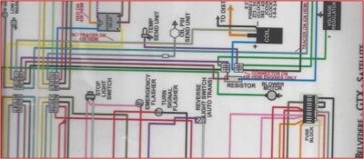
Connection of four wires that then tie in to the ballast resistor. The four that connect just above the ballast resistor in the wiring diagram attached. Mine connect in mid air in a wire nut taped with electrical tape. There had to originally be something that connected these four wires. What was it? Was there something originally attached to the firewall? A picture of whatever it was would help me a lot. A wiring diagram shows the four wires connect, but it is no help with regard to how.
Since it shows three wires connecting and then a fourth wire connecting to one side of the ballast resistor, can the three wires all have a loop connector on the end and be stacked on that side of the ballast resistor itself?
I took electricity in the 8th grade, but designed and made a remote detonator instead of working on automotive wiring, if that tells you anything. My teacher was fine with that and had another student bring in an M-80 we could set off outside during class. It went off, and I got an A. Today my teacher would have been contacting homeland security.
Thanks for your help.
Don
Jacksonville, FL


