• When you click on links to various merchants on this site and make a purchase, this can result in this site earning a commission. Affiliate programs and affiliations include, but are not limited to, the eBay Partner Network.

MAD/Nacho Electrical Wiring mods

Mopar4Speed

Well-Known Member
Local time
3:17 PM
Joined
Jul 15, 2019
Messages
105
Reaction score
35
Location
VA
Hi all, first post here. Have been reading off this forum for a bit now and wanted to discuss some changes between the two mods.

I like the idea of both mods but am leaning towards nacho's idea because i'd like to keep the ammeter in play. It saved me from melting my harness already (went full field) which gave me enough time to stop and shut the engine off and if it wasn't for the ammeter doing its job it wouldn't have ended well. The car in question is a 1966 coronet, low options (no a/c) and am using a 100amp tuff stuff alt.

So according to Nacho's upgrade, he does a parallel wiring routing for the charging and bat feed system. Now he said that he recommends 8ga charging and 10ga bat feed wires and leave the oem wiring in place. It seems really great but there is still power running through the bulkhead which may have fixed the wires/bulkhead from burning up completely but i thought to maybe it would be even better to disconnect the small gauge wires completely from the bulkhead and instead run a 6ga charge wire (rated to 150amps as per manufacturer) and a 8ga batt feed. I would the feed from the alt via 6ga straight to the amm but also hook up the original wiring inside the dash and de-pin the oem charging cable from the bulkhead. This would allow me to leave the dash side harness unmodified so it can feed the car as normal. Same deal for the for the batt feed remove/de-pin the oem wire and then replace with 14ga fuse link and 8ga wire. I put in a pic of nacho's diagram that i modified slightly to help explain.

If anyone could chime in with some insight or thoughts i'd appreciate it, Thanks
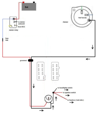
Alternator Charging system Bulkhead bypass.png
 
The reason for the parallel is to add extra wire so the smaller gauge wire doesn't get "overloaded" from higher amperage powering too much. As long as you're not running more current than what the wire allows, you should be fine to remove the smaller wire.
 
If anyone could chime in with some insight or thoughts i'd appreciate it, Thanks


Finally, someone who understands the real design weakness of the original Mopar charging system, vehicle and charging loads on the 50+ year-old Packard 56 connectors in the bulkhead. The parallel option may help shift the loads but removes the accuracy of the ammeter by definition. Better to replace the original 12 ga wires with 8 ga, or better, by-pass the bulkhead connections. Be sure the ammeter connections are tight but not too tight to damage/crush the insulators.
DSC09069.JPG
DSC09071.JPG

DSC09103.JPG
DSC01480.JPG


BTW, the parallel option is nothing new. Chrysler had a recall in the late seventies for C-bodies, a premade additional 12 ga, wire run that was installed between the alternator output and the fuse box batt bus, paralleling the original black charge wire run and bulkhead connector.
 
Last edited:
Thanks everyone, I appreciate the responses and for the info. My bulkhead wasn't too bad but I ended up getting a new engine harness and a new bulkhead connector (all with new packard terminals) anyway to make sure i don't have any issues after the car is back together. Moes, thanks for the link. I suppose i will use the 10 or 12ga fuse link instead of 14ga.
 
I've eliminated the ammeter in 2 of my cars so far, the rest will get the same treatment. Voltmeters are safer by a long shot.
 
Ammeters use live current, charging current through the bulkhead and under the dash. I read awhile back why Chrysler used ammeters but I cannot recall exactly why. They did eventually switch to amp gauges in the late 70s after numerous failures.
The wires get old, build resistance, get hot and melt things.

I believe they switched to voltmeters many for the safety aspect.
 
They did eventually switch to amp gauges in the late 70s after numerous failures.
The wires get old, build resistance, get hot and melt things.

Ammeters in these cars are not inherently dangerous as many like to suggest. Electrical resistance, and the resulting heat, are not caused by the aging of wires and connections, poor electrical maintenance and exposure to corrosion causing moisture is mostly to blame for the build-up of resistance over time. Ammeters have been used in automobiles since the beginning, the move away from them had far more to do with cost cutting than anything else. Ammeters provide much more real time information about a vehicle’s battery charge/discharge status than a volt meter or an idiot light. Chrysler’s ammeter problems began with the move to plastic ammeter/gauge frames in the late seventies Dodge trucks, again to cut costs. The Mad Electrical article that some like to promote, is specifically addressing the late-seventies truck ammeter meltdowns. Prior to that time, never saw ammeter problems at the dealer unrelated to improper ammeter connections or failed fiber insulators caused by over-tightening the ammeter connections. The blanket statement that the ammeter in these cars had numerous failures back in the day, just isn’t so.
 
Last edited:
For what it's worth, I did the parallel ammeter wiring on my 64, and using an 80 amp alternator. Working great!
Two of my sons are electricians. Nope, not on cars, but houses and buildings...point is, they use parallel wiring all the time. Told me golden rule on parallel wires, both must be the same gauge.
 
For the sake of this discussion, the only reason to run a parallel charge wire on these cars would be to reduce the current load on the original wiring and connectors, not wanting to take the time remove or replace the original wire, or the unwarranted fear that the ammeter will somehow spontaneously combust. Some AC circuit design theories don’t equate well to auto electric, matching the total voltage drop in the aged original charge circuit with another uninterrupted wire run to maintain a perfectly equalized load would be difficult and impractical.

I will add, all my cars, the cars I build for others, have up-sized alternators, up-sized charge wires (8 GA), by-passing the bulkhead connectors straight to the fully functional original ammeter, all performing flawlessly even with the addition of several non-original hi-current options, (all vehicle loads on the alternator side of the ammeter).
 
Last edited:
I will add, all my cars, the cars I build for others, have up-sized alternators, up-sized charge wires (8 GA), by-passing the bulkhead connectors straight to the fully functional original ammeter, all performing flawlessly even with the addition of several non-original hi-current options, (all vehicle loads on the alternator side of the ammeter).

I totally agree with that, the ammeter has it's place in there in my opinion. Besides who would want a dead gauge in there anyway?
 
So, I have a 100amp alt and it's a 1-wire hookup with the internal regulator. Am I supposed to just leave the field plug off? Also for the alt I read the card it comes with that says I have to ground the other brush to the case but when I look it, it seems to be grounded to the case already. The only thing i see is the stud (not b+) on the side, is that my ground i'm supposed to hook the wire to?
 
So, I have a 100amp alt and it's a 1-wire hookup with the internal regulator. Am I supposed to just leave the field plug off? Also for the alt I read the card it comes with that says I have to ground the other brush to the case but when I look it, it seems to be grounded to the case already. The only thing i see is the stud (not b+) on the side, is that my ground i'm supposed to hook the wire to?

I would think that "b+" means battery positive, do no ground that.
 
So, I have a 100amp alt and it's a 1-wire hookup with the internal regulator. Am I supposed to just leave the field plug off? Also for the alt I read the card it comes with that says I have to ground the other brush to the case but when I look it, it seems to be grounded to the case already. The only thing i see is the stud (not b+) on the side, is that my ground i'm supposed to hook the wire to?

Normally, internally regulated alternators, other than the alt output post, just need a “exciter” wire, a switched ignition trigger voltage, on a Mopar that would be ignition 1(blue wire in the engine harness).
Some PowerMaster “one-wire” alternators just need to have the Alt output wire connected, auto-switches with alternator rotation. No exciter voltage needed.

The “ground one field terminal” language would likely refer to using a later Mopar externally regulated dual insulated field alternator on an older mechanically regulated Mopar.
What alternator are you working with?
 
Last edited:
I would think that "b+" means battery positive, do no ground that.
Yes by B+ I am referring to the charge cable stud from the alternator output stud.

There is another small stud on the case of the alternator. The alternator is a march performance p590 which is basically just a tuff stuff alternator with a march serpentine pulley on it. It's a square back alt with the one field wire grounded to the case. Did not come with any instructions or recommendations apart from the one card stating that I need to ground the alternator and that they provided a small ground wire but no diagram or other instruction. Just hoping someone else on here got an alternator from them and knows what they are getting at.
 
Some aftermarket manufactures of Mopar alternators do have ground studs in the cases, seems they don’t trust installers to insure an adequate ground path through its mounting. Never used them.

The Tuff Stuff repo Chrysler “1-wire” alternators appear to be not really internally regulated at all, has a small regulator screwed to the back of it. Connected to one the output stud and one field terminal. On a squareback alt, this would require the other field terminal to be grounded. Normally they just replace an insulating washer on one terminal with a metal washer. Should only need to connect the output wire to have it work correctly.
 
I will get deep on this later ( I'm barelly waking up LOL ) but just some initial notes:

The "Nacho's upgrade" is just an idea taken from the original Chrysler idea installed on fleet cars, using a high load path throught the firewall.

What's the difference on my suggestion? If your car still have an useable stock path, meaning non burnt or melted down at bulkhead, the stock paths can be still used and install a parallel path.

What's the advantage on keep the original path on alt side at least? The main splice inside the cab will be still beng feeded from alt by two 12 gauge wires, the one coming from bulkhead and the line coming from ammeter where you are installing the parallel path, thing what won't happen removing the stock one and installing just the larger bypass through the firewall, where is true you can use a 8 gauge wire but the main splice will be still getting just the 12 gauge wire between amm and splice.

After this, STILL installing the bypass or parallel wire up to ammeter, if you keep the stock output alt the swinging ammeter reading will remain the same, so then, the loads coming and going throught the ammeter won't be saved and heat will be playing yet there. BOTH upgrades must be worked at the same time... wiring to save the paths and alt to save the loads at ammeter.

Remember your car will be still requesting same load no matter where it comes from, alt, batt or both together. If you save your car from take loads coming from batt and the most as posible from alt, the ammeter won't get the load going throught when alt is not enough, so all the loads will be playing from alt side, meaning out of the ammeter play. No load there, no heat there.

At the same time, if your batt never or barelly gets discharged because you got a good alt, then the battery won't suck loads to be recharged back, once again, no load to charge running throught the ammeter.
 
Last edited:
Aaand EVERY device, stock and additions installed on your car MUST be sourced from alt side, never from batt post ( with just minor exceptions ), because THIS will stress the ammeter too adding unnecesary loads there, aside get wrong readings. This has being a HUGE mistake made along the years on ammeter equipped cars, blaming then the "unsafe" ammeter feature, where maybe the unsafe feature on this maybe is behing the steering wheel.
 
Auto Transport Service
Back
Top