• When you click on links to various merchants on this site and make a purchase, this can result in this site earning a commission. Affiliate programs and affiliations include, but are not limited to, the eBay Partner Network.

msd 8386

mike smock

Well-Known Member
Local time
8:40 PM
Joined
Jan 28, 2019
Messages
68
Reaction score
15
Location
iowa
am i overthinking this? first off new 383 engine, new msd 8386 motor was ran on a stand with the msd. my question is how do i wire it in my 1969 road runner???? i know the basics, no ballast resiter needed or orange control box (never had one). can somebody please post a picture on how they did the wiring or detailed instrutions ( i still have the factory wiring harness and original colored wires) any info is great. I hate wiring. hope this all makes sense. also what do i do with the old wires from the ballast resister, just cut and remove them?
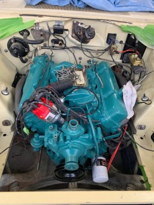

engine.jpg
 
Use the blue wire from the Ignition switch...colour is irrelevant ...as long as it goes to the correct location.

The blue wire will likely be found at the ballast resistor....which is no longer required with a "Ready to Run" distributor.
 
Just like @kiwigtx says, take it from either side of the ballast - ONLY, if you bypass the ballast resistor first. The 8386 msd requires you to do that. Some people who aren't into looks will just connect the wires that used to go to each side of The ballast together and run a new red one for you msd ready to run if they choose to remove the ballast resistor.

I wanted the look of The ballast resistor, so I soldered a solid wire between the two terminals on the back side of the ballast, thus achieving the same thing as just connecting the wires together manually. Some ballasts are hollow on the back, others are not. If yours is solid buy a hollow one to do this.

On the picture the red wire is the one I added which goes to the distributor.

The others are self explanatory and as per the diagram that kiwigtx provided
732EA02C-001D-4ECC-B16D-11BD9F5CDAD4.jpeg
 
Just like @kiwigtx says, take it from either side of the ballast - ONLY, if you bypass the ballast resistor first. The 8386 msd requires you to do that. Some people who aren't into looks will just connect the wires that used to go to each side of The ballast together and run a new red one for you msd ready to run if they choose to remove the ballast resistor.

I wanted the look of The ballast resistor, so I soldered a solid wire between the two terminals on the back side of the ballast, thus achieving the same thing as just connecting the wires together manually. Some ballasts are hollow on the back, others are not. If yours is solid buy a hollow one to do this.

On the picture the red wire is the one I added which goes to the distributor.

The others are self explanatory and as per the diagram that kiwigtx provided
View attachment 935344
PERFECT just what i was looking for, i thought i had it figured out just wanted to double check, so you just soldered the red wire onto the other wire?
 
You need to tie the dark blue and the brown wires (at the ballast connector) together then feed to power the box on/off. The blue wire is hot in run only. The brown wire is hot in crank only. You need both. Or you can feed the box directly from battery to a toggle switch. This switch will then control ignition on/off. The key will still do the cranking.
Doug

No. I had a spare female spade type connector. I separated the connector from the plastic housing, cut the existing wire and then crimped the existing wire and the new red wire into the new connector, put it back in the hard plastic housing and then plugged it on.

But I suppose you could just solder it, yes.

Don’t forget to bypass the ballast with a solid piece of wire.
 
You need to tie the dark blue and the brown wires (at the ballast connector) together then feed to power the box on/off. The blue wire is hot in run only. The brown wire is hot in crank only. You need both. Or you can feed the box directly from battery to a toggle switch. This switch will then control ignition on/off. The key will still do the cranking.
Doug

When you solder a solid piece of wire on the back of the ballast it doesn’t matter what side of the ballast you put the red wire on as it’s one continuous loop.
 
Last edited:
Edit

Actually I’m full of it. The red wire I added was for the electric choke. I’ve got a case of CRS (can’t remember ****! Lol). Regardless, if you bypass the ballast the way I described you can continue to just use the factory blue wire which normally goes to + side of the coil. Red from the distributor also goes there, again as per the kiwigtx diagram.... good luck

Just like @kiwigtx says, take it from either side of the ballast - ONLY, if you bypass the ballast resistor first. The 8386 msd requires you to do that. Some people who aren't into looks will just connect the wires that used to go to each side of The ballast together and run a new red one for you msd ready to run if they choose to remove the ballast resistor.

I wanted the look of The ballast resistor, so I soldered a solid wire between the two terminals on the back side of the ballast, thus achieving the same thing as just connecting the wires together manually. Some ballasts are hollow on the back, others are not. If yours is solid buy a hollow one to do this.

On the picture the red wire is the one I added which goes to the distributor.

The others are self explanatory and as per the diagram that kiwigtx provided
View attachment 935344
 
When I had the same msd on my 67 383, I did the same mod to my ballast, but both sides originally had 2 wires, with one on the hot run side going to the coil.
I just powered the distributor off the coil as in the above msd diagram.

Doesn't the 69 have that same coil wire already there?
 
When I had the same msd on my 67 383, I did the same mod to my ballast, but both sides originally had 2 wires, with one on the hot run side going to the coil.
I just powered the distributor off the coil as in the above msd diagram.

Doesn't the 69 have that same coil wire already there?
It does
 
than
Just like @kiwigtx says, take it from either side of the ballast - ONLY, if you bypass the ballast resistor first. The 8386 msd requires you to do that. Some people who aren't into looks will just connect the wires that used to go to each side of The ballast together and run a new red one for you msd ready to run if they choose to remove the ballast resistor.

I wanted the look of The ballast resistor, so I soldered a solid wire between the two terminals on the back side of the ballast, thus achieving the same thing as just connecting the wires together manually. Some ballasts are hollow on the back, others are not. If yours is solid buy a hollow one to do this.

On the picture the red wire is the one I added which goes to the distributor.

The others are self explanatory and as per the diagram that kiwigtx provided
View attachment 935344
thanks for the help, fired her up last night for the first time in 40 years!
 
Auto Transport Service
Back
Top