Hope you get it worked out
OK so I had a further look at this today.
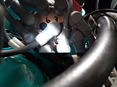
I took a spare cap and drilled a good sized hole inboard of plug 1 terminal. When running at 600rpm with vac disconnected and plugged (ported vacuum so should not be any vacuum advance anyway) with 18 degree initial timing I took a note of the rotor. It is past the 1 terminal and almost half way to the 8 terminal on the cap See picture 1.
When vacuum advance is reconnected I can see how this could cause a misfire as the pickup and the plate that it is mounted on further rotate in a CW direction in relation to the reluctor when starting to apply vacuum advance.
Here's where I am confused to the point of becoming annoyed with myself!
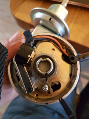
When the pick up and reluctor are perfectly inline (pic 2) with the distributor removed and on the bench, the rotor points centrally at cap position 1. Indicated by 1 line on outer casing. The 2 lines show where the rotor is pointing when at idle 18degress. I assume I want the rotor pointing at cap position 1 at idle 18degrees. This however would put the reluctor to pick up out of alignment by nearly 1/3 of gap between reluctor peaks. I assume the earlier trigger is exactly what I am looking for and I should stop getting hung up on the reluctor being bang on inline so long as the rotor points at terminal 1 when firing? This is the bit that has had me confused. 1 minuite I think I understand it then as soon as I look at practically I'm lost again!!
I've tried moving the reluctor to different positions but none line up as I would need. I've now marked the reluctor and will mill a new roll pin slot tomorrow. No big deal. O considered another 2 options..
1. What's to stop me making the base plate that holds the pickup adjustable? I could do this by slotting the casing where the retaining screws go through. Edit, after looking at this option I can't do this as the vac advance is connected to the base plate and limits radial positioning.
2. What's to stop me from reindexing the rotor arm. Don't fancy this as a fix as every rotor arm replacement would lead to modification required. - Not an option I'd chose. Looks like milling a new slot will be easiest solution.
I can see that phasing is a discussion that often leads to confusion but I really want to get my head around this. Both to learn and set my engine up best I can. I appreciate you guiding me along.
Another bit I don't understand is that when the vacuum adv comes in it moves the rotor in a CW direction ( so I'll adjust to make rotor to cap line up as middle as possible over the full movement range) but will the pickup also moving clockwise and getting closer to the next reluctor pole not cause issues? You see I keep flicking between reluctor and pickup relationship and rotor to cap relationship and confusing myself. Please tell me i just need to concentrate on rotor to cap alignment as central ram as possible through the rpm range and that's it!!! ARGGGGGHHH!!!
Thanks for bearing with me.


