• When you click on links to various merchants on this site and make a purchase, this can result in this site earning a commission. Affiliate programs and affiliations include, but are not limited to, the eBay Partner Network.

Torque strap

GOLDMYN

Well-Known Member
Local time
9:46 PM
Joined
Jun 17, 2011
Messages
314
Reaction score
394
Location
chilton, wi
Show your torque strap , front left-side of the engine. I've installed a small chain. not that I'll be doing any burn-outs but with a manual transmission, you never know.
 
I got rid of the chain in 1979...
beerestoration2017 109.JPG
beerestoration2017 110.JPG
 
Mancini Racing sells a factory looking fail safe mount that fits great and works even better. Thier part number is MREMAGMNTB
 
Last edited:
I tend to over-do things, was worse in my younger days.

IMG_20210116_092540222~2.jpg
 
Or.... a solid motor mount, at least on the driver's side
 
I like that one as well.
Do you have a link to the vendor on Ebay ?
No link it was just a guy who listed some parts. After I purchased it, he asked what is that part for :rolleyes:
I know that Chrysler used them in HP cars and taxi cabs in the late 60’s and early 70’s.
 
No link it was just a guy who listed some parts. After I purchased it, he asked what is that part for :rolleyes:
I know that Chrysler used them in HP cars and taxi cabs in the late 60’s and early 70’s.
Thanks for showing how to mount it, I have two of them and had no idea how to do.
 
Mine is a heim end I scavenged out of some factory, and an aluminum bar.

The vertical bar is steel, and I could lighten it some.
 
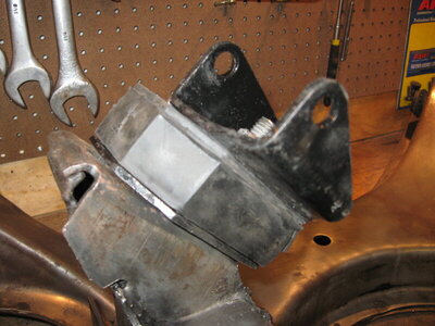
Don't use one. I modified my driver's side motor mount so it acts as a torque strap and can't come apart.

I used grade 8 hardware to pin the two halves of the motor mount together so they can't pull apart. This is not rocket science and is an easy job. This mount is not under compression when torque is applied, it is under expansion so the idea is to limit this expansion.

This is a 1/8" plate that has been drilled to fit the chassis side of the mount. That's the two bolt side. There are two tapered holes drilled to accept two 3/8" grade 8 bolts as well. These are the holes at the corners.

IMG_5626a.jpg


The plate was fitted on the motor mount and two holes were drilled through the rubber and engine side plate to accommodate the additional bolts. Once finished the plate was removed and two grade 8 bolts with their heads cut off were inserted into the holes and welded in place. The welds were then ground smooth on the chassis side so the mount will sit flat on the cradle. This is what you see in the above picture.

IMG_5629a.jpg


Here you can see the studs sticking through the engine side of the mount. Just a couple lock nuts needed to complete this job.

IMG_5633a.jpg


And here you see the finished mount (engine side) temporarily bolted to the cradle. It's easy to see how the rubber mount is sandwiched between the two metal plates which limit it's expansion when torque is applied. So, no need for a torque strap.

IMG_5632.JPG
 
Last edited:
Auto Transport Service
Back
Top