• When you click on links to various merchants on this site and make a purchase, this can result in this site earning a commission. Affiliate programs and affiliations include, but are not limited to, the eBay Partner Network.

Wiper motor and switch discussion and info

Passion4Mopars

Well-Known Member
Local time
4:37 PM
Joined
Jun 16, 2010
Messages
125
Reaction score
42
Location
Sunny FL...again
The switch determines if the motor is three speed or variable speed, otherwise everything is the same, they build the same but if I put the same motor on a three speed switch, it's a 3 speed, if I take that motor and hook it up to a variable speed switch, it's variable.
 
Wrong, variable speed wiper motors have a shunt field and you vary the speed by changing the resistance in series with the shunt field. The switch has a variable resistance (rheostat) built into it.
 
I restore these motors and I build with a 3 speed switch mounted on my bench. If I take the same motor I just built and it runs with 3 distinct speeds and hook it up to a variable speed switch it runs variable speeds. The motor is exactly the same. The switch determines if the motor runs with 3 distinct speeds or variable speeds, and did on all mopar wiper motors until the intermittent function was introduced.

But if this is a black and silver type motor (General Industries/Leece Neville) and you're looking for visual differences, it's vspeed/3speed if it has four wires going into the bulkhead connector, 2 speed if it has 3 wires going into the bulkhead connector.

BUT, the motor runs at variable speeds when connected to a variable speed switch (variable resistor in the circuit) and three distinct speeds when connected to a 3 speed switch. The switch determines the difference.
 
So if I understand you correctly and I need a new wiper switch for my '66, could I substitute a 3-speed switch for the VS it now has? Does the 3-speed switch use a different wiring harness?
 
If it fits in your dash without you having to do modifications because of stem length or rocker width, etc. it's fine to use. They wire the same
 
Good to know. The VS function works fine, but the switch is not powering the washer pump. Troubleshooting is on my list along with 18 other items.
 
Great information from Jim at JS Restorations provided to me because too often we have a motor and need to narrow down, is it motor or is it switch? No sense in restoring the motor, etc. if on return it's going to act like it did before restoration/repair.

Switch Terminals to Wire Color Connections: (2864014 Three Speed Rocker Wiper Switch)
A = Brown w/ White Tracer 18 gauge (Bulkhead Terminal Position E)
A = Brown w/ White Tracer 24 gauge (Through Dash Harness and back to Terminal R1)
B = Pink
P = Blue (Bulkhead Terminal Position H)
W = Brown (Bulkhead Terminal Position M – Washer Pump Motor)
F1 – Red (Bulkhead Terminal Position F)
F2 = Green (Bulkhead Terminal Position G)
B/U = Brown (Jumper Through Dash Harness to Washer Switch. Connector has a dog house shape opening on side to pass over the barb that sticks out on the terminal.)

B to B/U = B voltage in across the internal circuit breaker. Always on no matter what speed or off position to B/U. B/U Voltage After Circuit Breaker

The following connections should all be reading 0 ohms, except as noted, when active. Any connection combination not mentioned should not show a reading. The switch must be grounded from switch frame to -12V if being tested without the switch secured into the dash frame, when bench testing with jumpers or the actual dash harness to the wiper motor.

In the OFF position:
B to P
A to F2
F1 to Chassis Ground

In On Low through High speed positions:
B to F1 {(0 Low) (-8 Medium) (– 30 High)} *Note 1
A to F1 {(0 Low) (-8 Medium) (– 30 High)} *Note 1
B to A
F2 to Chassis Ground

*Note 1: The Medium speed impedance is only able to measured when the switch is plugged into the dash harness. There is a short jumper wire shown in the factory manual between terminal A and terminal R1. The -8 Ohm resistance is created from a solid thin 24 gauge wire that jumps between these two positions inside of the dash harness. Terminal A on the harness should have two brown with white tracer wires.

Wiring through the bulkhead connector:
E. Brown w/ White Stripe
F. Red
G. Green
H. Blue
W. Brown (Washer Motor)
__________________________________________________________________

Three Speed Wiper Motor Bench or Firewall Four Wire Terminal Test: *Note 2

Forward (Slow)
12V+ to Red & Brown
Green to Motor Ground Strap
12V- to Motor Ground Strap

Forward (Fast)
12V+ to Brown
Green to Motor Ground Strap
12V- to Motor Ground Strap
Red Not Connected

Reverse (Park)
12V+ to Blue
Green to Brown
Red to Motor Ground Strap
12V- to Motor Ground Strap

*Note 2: If the motor does not move forward initially, try the reverse test, once. If the motor returns to the park position and stops, continue with testing the forward motion. The motor will not move forward if the last power applied was moving the motor in reverse and did not complete the park motion.
 
Last edited:
I have worked on many wiper problems over my years as a tech. Now when you say variable are you refering to intermittant wipers ? Thats what I was thinking you mean. Most wipers I worked on were either a 2 speed with a different brush for high and low and some like some GM ones were 3 speed with the shunt winding as the shunt could be grounded or grounded through a resister to control 2 speed and the third speed high would take the shunt out and run the series field full current for high. I remember many Mopars also use a ballast type resister mounted on the motor which I believe was a two speed wiper. I would have to look at the wire diagram for what ever model I worked on as I worked on many different brands and dont remember all in my head. Also many of the intermittant wipers I worked with would spike the low circuit and then it would run through sweep and then park just like you turned the wipers off and then anywhere from about 6 to 30 seconds would spike volts in the low again and once the wipers moved the park circuit run it through one sweep. Many of the newer cars would use a module to watch the ground also as when the module would see the park switch ground it would stop the wipers. And some wiper systems would actually run the motor in reverse to park them and many used the low circuit for park. But I worked with Mopar , Ford GM and even American Motors wiper systems over the last 35 years. My best tool was having the wiring diagram so I knew just how the system worked when I looked at the wire diagram. Ron
 
Here's some good info on shunt wound DC motors. Wiring diagrams are almost a MUST. I have some posted on my website in the blog area. As time permits I'll try to post some different years. As Time permits. That's funny, right now my plate is so full my jello is wiggling off

http://www.electrical4u.com/shunt-wound-dc-motor-dc-shunt-motor/
 
Last edited:
Real good thread! Good info.

I got a question.........

Say a person has an A-Body with a 2 Speed wiper and a foot pump, how does one covert that to a washer system w/electric pump? Does it involve just changing the switch & pump? Or would the Wiper Motor be different as well?
 
Wiper

On my 66 Satellite with variable speed wipers to activate the washer mode all you do is push in on the wiper switch knob.
 
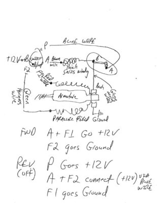
Thought I would add some additional data to supplement Kim and Jim's info. These wiper motors are really a Compound motor when you take them apart. Here is the current flow path through the wiring, switch and motor:

Circuit path for Off (reverse motor and park): +12V from B to P in switch thru blue wire to motor cover terminal point (A) contact. Thru Points (Park off when they open from cam) thru copper arm to terminal point (B) on cover with Green wire to motor armature brush, thru arm to grounded brush. Also at terminal (B) with green wire is thick series field winding. Thru series field to brown wire back to switch position A. A to F1 thru red wire to thin parallel main field winding. Thru windings back to harness green wire to F2. F2 is grounded via switch. This puts the series winding in series with the field winding that is always in parallel with the armature winding. This is reverse until the cam on internal gear opens the points and turns off +12V coming from Blue wire.

Circuit path for On (Low): +12V from B to B/UP in switch to A terminal in switch thru brown wire to thick series field winding. Thru thick series fielding winding to Cover terminal (B). Thru Green wire also attached a terminal (B) to armature Brush. This put thick series field winding in series with armature making it a compound motor with better torque characteristics. Thru the armature to the grounded brush. Additionally at the switch position A is connected to Position F1. Thru Red wire to parallel thin field wire. Thru field windings thru Green wire to switch position F2. F2 is grounded at switch.

This path through motor remains the same for medium and high speed with the only difference is the switch inserts additional resistance. For a DC Compound (or Shunt motor) when the current is reduced through the parallel field winding (by adding a series resistance) the motor speeds up. By flipping F1/F2 polarity you change direction of the field current while keeping armature current same direction. This reverses motor rotation.

Note that when the motor goes forward the cam will come off the point contact arm and allow them to close. This will energize the blue wire at terminal (A). The wire returns to switch position P which is open when the switch is on any ON speed. Low, Med, High.

The Green wire from Terminal B to armature brush is not part of the harness wires. Separate green wire.
Crude drawing attached.

Wiper002.jpg
 
Have you done any recent work under the dash? Check the grounds and wiring to switch.
 
If it is a 3 speed, it may be the cam or lockout is broken and the gear never opens the switch when it tries to park. When the Switch is in the off position, it always energizes the blue wire for park. It is the switch in the cover that kills power to motor when wipers get to the parked position. The cover has a lever that engages a pair of levers on the worm gear for changing the cam orientation.
 
Right now all dash wiring is in a box, car is completely gutted. It had been working fine, hadn’t done anything under the dash. If I held my mouth right, wiggled the switch knob a little, I could get them to park. The variable part worked fine.
When I was taking the wiring out of the dash, I noticed that switch was not really tight. I am hoping that might be the problem.
Electrical problems are one of weaker points.
 
If it is a 3 speed, it may be the cam or lockout is broken and the gear never opens the switch when it tries to park. When the Switch is in the off position, it always energizes the blue wire for park. It is the switch in the cover that kills power to motor when wipers get to the parked position. The cover has a lever that engages a pair of levers on the worm gear for changing the cam orientation.
 
@Passion4Mopars i need your advice. I was checking my 3 speed wiper switch according to the manual page 8-79 below. At position "Medium (3 Speed Only)" it says there should be a connection between A and R1, but it isnt. After opening the switch, i saw there cant be a connection between those at Medium. So whats wrong here? Its definitely a 3 speed switch for a 68 b body!
 
Auto Transport Service
Back
Top