• When you click on links to various merchants on this site and make a purchase, this can result in this site earning a commission. Affiliate programs and affiliations include, but are not limited to, the eBay Partner Network.

Wiring upgrade help

Rakishi64

Member
Local time
11:51 PM
Joined
Dec 16, 2019
Messages
21
Reaction score
13
Location
Florida
I bought a 72 Charger last November and have been slowly working on improving it. Right now I am trying to identify what's been done to the wiring so I can see if an upgrade/rewiring is still needed. I've read about some people doing a parallel system, while keeping the stock ammeter, to help handle a new alternator and accessories. I am unsure if that is what has been done here.

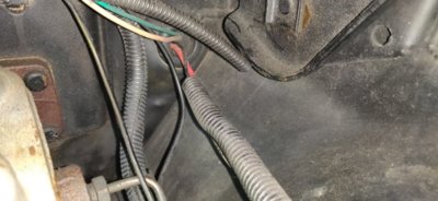
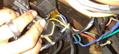
There is a second thick gauge red wire coming from the starter relay, through the bulkhead to a 12v relay under the dash on the driver's side. A yellow wire is spliced in to the red wire and connects to a second relay. On the first relay there's a green/white wire that runs back through the bulkhead and turns to a brown/white wire that connects to the ignition ballast. The third wire is a blue wire that is spliced to a black wire in the steering column. The final wire is a green wire that connects to a stud under the dash which has another green wire that connects to the second relay.

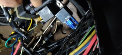
On the second relay there is the abovementioned yellow, and the green wires. The last two wires are a yellow/brown and brown wire that connect to a cluster of wires under the steering column.

Is this just another way to make a parallel system to handle the aftermarket radio and other accessories? With this system is adding a new alternator below 85amps safe if I ensure the correct wire thickness coming from the battery and alternator? Thanks in the advance.
wire diagram of car.png
starter relay .jpg
starter relay w/2nd red wire bulkhead frm engine.jpg first 12v relay.jpg 1st 12v relay second 12v relay.jpg 2nd 12v relay
 
Last edited:
This is not a parallel circuit. My guess is someone attempted to get keyed 12V power to the ballast. That red wire going to the starter relay in the top picture is a factory wire. It sure looks like the wire that goes to + on ammeter. Where is the negative ammeter wire? If this was my car I would remove the two under dash relays and associated wiring and go from there. Get that fixed first before any alt upgrade. You will need a schematic for engine compartment and under dash.
Frank
 
Frank's right. The green wires from the relays to the dash stud are grounds. The red wire with the yellow wire spliced in is the power feed to both relays. On these year mopars the blue and brown wires are switched power. One is for cranking power the other is Run power. I think the blue is run and brown is cranking. So the double green is your run supply to the ballast from relay 1 and the yel brown wire probably finds its way back to the + side of the coil. Way too messed up to run. It should be fixed properly then move on to the next phase. The scariest part is the size of that red feed wire and no fuse or fusible link to be seen. The schematic should be on the site here somewhere. A 71 would do in a pinch but might not be exactly the same.
My guess is the ignition switch in the column is bad and this is how they bypassed it.
 
Last edited:
Thanks for the response guys.

On the starter relay there are 2 red wires with this set up. I thought the red wire with the fusible link went to the ammeter, is that wrong? I also thought there was only one red wire from the starter relay with the stock set up.

I have the shop manual at home and was using the engine compartment wiring diagram to try and identify the wires, didn't do so well obviously.
Yes, disconnect red wire without the fusible Link. Or put a fuse (25 or 30 amp) or circuit breaker on it. It has full unchecked battery power which can burn the car to the ground if it shorts. The one with the fusible link is the main power feed that goes to the Amp meter then out to the harness and fuse block.
Not your fault, I've seen tons of spaghetti wiring. I always pull it and get back to working factory stock just so I know where I stand. Like I said, don't be surprised if the ignition switch in the column is bad when you do. I'll be checking back to see how you are doing.
Sounds simple enoguh, thanks again for the help..hopefully it won't be too much of a pain.
 
Auto Transport Service
Back
Top