• When you click on links to various merchants on this site and make a purchase, this can result in this site earning a commission. Affiliate programs and affiliations include, but are not limited to, the eBay Partner Network.

Alternator Wiring

NO....The BLUE wire provide the electronic voltage regulator the system's reference voltage of the voltage present at the battery AND the switched source from the ignigion switch. The GREEN wire RETURNS the current psth from the alternators field.....blue wire power going in TO the alternators the GREEN wire, via the alternator regulator to GROUND, thru the internal transistors. IT HAS NOTHING TO DO WITH RACE PROPOSES AS STATED.
NACHO....you need to not to explain or exemplify sonething that is incorrect....if you do not understand the how the system operates.....just ask.
BOB RENTON
Bob, is having all these wires tied together going to cause issues?
blue (run) to regulator, Brown (start), MSD red, dist. red, and new wire from regulator to alternator

kind of a mess. I don't have a resistor, and the MSD box and dist. need both the blue (run) and the brown (start) wires. The regulator apparently also needs the blue (run) wire

The wiring i was referring to is strictly for the alternator and voltage regulator inerconnect wiring. The original person introduced connections with the ignition system and the elimination of a ballast resistor or if it was required....the two system are independent of each other.....likely the cause of your hesitancy....
BOB RENTON
 
The wire to regulator IS ALREADY running from same line! Don’t overthink it.

wiper blue wire is a way diff signal and has nothing to do with ign system.
 
The wire to regulator IS ALREADY running from same line! Don’t overthink it.

wiper blue wire is a way diff signal and has nothing to do with ign system.

What exactly does this mean? ...."way diff signal" and has nothing to do euth the ignition system ....what are you trying to say ?
BOB RENTON
 
What exactly does this mean? ...."way diff signal" and has nothing to do euth the ignition system ....what are you trying to say ?
BOB RENTON[/QUO
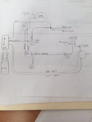
so would the attached diagram work? if i could get 12v (w/ key on) to the regulator from something other that the factory blue wire, like the wiper motor, then i could avoid having everything else tied to the regulator...

and wouldn't the fusible link go between the alt. and the bulkhead/ammeter?

IMG_8610 (1).JPG
 

NO... IT DOESN´T WORK!!!

once again, forgett the blue wiper wire! its sourced from Accesories and is powered just with wipers off to parking the wipers.

The old regulator already have its wire, just use it! New regulator uses the same.

and don't put a fuse link on alternator wire! the only source able to keep feeding a short is the battery, even more with engine off. With engine running a short is able to stall the engine, while the batt keeps the current flowing to feed the short.

without mention, the alt wire with a discharged batt handles more amps than the batt wire to recharge the batt or feed any other device on car. Will be a very sensible point to install a fuse link without any extra protection purpouse.
 
Last edited:
NO... IT DOESN´T WORK!!!

once again, forgett the blue wiper wire! its sourced from Accesories and is powered just with wipers off to parking the wipers.

The old regulator already have its wire, just use it! New regulator uses the same.

and don't put a fuse link on alternator wire! the only source able to keep feeding a short is the battery, even more with engine off. With engine off a short is able to stall the engine, while the batt keeps the current flowing to feed the short.

without mention, the alt wire with a discharged batt handles more amps than the batt wire to recharge the batt or feed any other device on car. Will be a very sensible point to install a fuse link without any extra protection purpouse.

WHAT YOU ARE SAYING MAKES ABSOLUTELY NO SENSE. What are you trying to say....is it about the charging system and the various connection points or the park circuit of the wipers or ???? I have no clue as to your point is...
BOB RENTON
 
The blue wired, power/reference supply to the alternator field and regulator needs to remain connected to ignition 1 (blue wire in the engine harness) as it was originally. It is not to be connected in any way to any leads at the wiper motor. You show the Ign 1 (blue) & Ign 2 (brown) tied together, as needed by the MSD, connect your regulator & field power/reference there as originally designed.

Again, with an operational factory ammeter installation, all vehicle loads need to be on the alternator side of the ammeter to function as designed. Nothing connected directly to the battery, including the MSD power leads.
 
Last edited:
WHAT YOU ARE SAYING MAKES ABSOLUTELY NO SENSE. What are you trying to say....is it about the charging system and the various connection points or the park circuit of the wipers or ???? I have no clue as to your point is...
BOB RENTON
just want to know if the charging system will work correctly if i get power to the voltage regulator from a 12V IGN source at the wiper motor (12v only when key is in run position)

or does the voltage regulator HAVE to utilize the dark blue "run" wire coming from terminal "N" on the bulkhead connector for the regulator and charging system to work properly
 
The blue wired, power/reference supply to the alternator field and regulator needs to be remain connected to the ignition 1 (blue wire in the engine harness) as it was originally. It is not to be connected in any way to any leads at the wiper motor. You show the Ign 1 (blue) & Ign 2 (brown) tied together, as needed by the MSD, connect your regulator & field power/reference there as originally designed.

Again, with an operational factory ammeter installation, all vehicle loads need to be on the alternator side of the ammeter to function as designed. Nothing connected directly to the battery, including the MSD power leads.
ok, so my charging system will be fine if i have the blue IGN 1, MSD small red, the distributor red, the brown IGN 2, and alternator new 2nd field wire ALL tied into the voltage regulator??

for the ammeter, should i put fusible link on alt. side AND battery side of ammeter to be safe? or should i just bypass it?

do i need to land my MSD power lead and electric fan power leads on the alternator BAT post to keep it on the alternator side of the ammeter?? i currently have them landed straight to the battery positive post
 
WHAT YOU ARE SAYING MAKES ABSOLUTELY NO SENSE. What are you trying to say....is it about the charging system and the various connection points or the park circuit of the wipers or ???? I have no clue as to your point is...
BOB RENTON

I really dunno if you looked at the diagram posted by Landon. He has been asking again and again ( then posted a diagram ) about source the regulator from the wiper blue wire!!!
 
ok, so my charging system will be fine if i have the blue IGN 1, MSD small red, the distributor red, the brown IGN 2, and alternator new 2nd field wire ALL tied into the voltage regulator??

Short answer, yes, as originally designed.

for the ammeter, should i put fusible link on alt. side AND battery side of ammeter to be safe? or should i just bypass it?

As Nacho describes, the fusible link goes at the battery side of the charging circuit, normally at the starter relay. It protects the larger gauge unfused wiring from the current potential only available from the battery. No need for a fusible link on the alternator side.

do i need to land my MSD power lead and electric fan power leads on the alternator BAT post to keep it on the alternator side of the ammeter?? i currently have them landed straight to the battery positive post

All added loads need to be on the alternator side of the ammeter if running a factory ammeter config. Alternator output stud will work in most cases, be sure to have circuit protection close by for those circuits added
 
Short answer, yes, as originally designed.


As Nacho describes, the fusible link goes at the battery side of the charging circuit, normally at the starter relay. It protects the larger gauge unfused wiring from the current potential only available from the battery. No need for a fusible link on the alternator side.


All added loads need to be on the alternator side of the ammeter if running a factory ammeter config. Alternator output stud will work in most cases, be sure to have circuit protection close by for those circuits added
 
So i ran it last night like my diagram showed, voltage reg. getting 12v (key on) from wiper motor. It ran, but was discharging on the ammeter and sounded like it was misfiring. Battery showed 11.5 volts at idle. Can anyone explain? I tied 6 wires together (IGN 1 blue, IGN 2 brown, MSD box, dist, alt field, and volt reg blue) and it ran better and seemed to be charging finally. Battery showed 13+ volts at idle. This is how I had it wired before, I guess the squareback alt. & newer style voltage reg upgrade is the reason it is charging now.

I am thinking now I will put a terminal block on the firewall for the 6 wires just to clean up the mess.

Thinking about putting a 2nd terminal block tied to BAT on the alternator and landing my MSD and electric fan feeds here to get them off the battery "after the ammeter." Any issues with that??
 
So i ran it last night like my diagram showed, voltage reg. getting 12v (key on) from wiper motor. It ran, but was discharging on the ammeter and sounded like it was misfiring. Battery showed 11.5 volts at idle. Can anyone explain?
As Nacho already attempted to explain, there isn’t a clean ign1 switch power source at any of the wiper motor terminals. The wiper system is on the ignition switch accessory circuit, not ign1. Any voltage measured with a VOM appearing to be key-switched voltage on those terminals is likely a winding back-feed of some kind. Would not support a load of any kind, and nowhere near an accurate line voltage reference point.

Speaking of reference voltage, check your voltage drop between your “six wire” splice and the battery post while running. Pretty common to have resistance at the ignition switch and/or the ignition switch Molex connector, at the lower steering column, also the Packard terminal for ign1 in the bulkhead connector. Any voltage drop across these connections will present an inaccurate reference voltage to the regulator.
Thank you; that explains it much better.

I will have to check my voltage at the 6 wire connection vs at the battery. Check it running or just key on? Also, is there anything I can/should do if there is voltage drop?
 
As Nacho already attempted to explain, there isn’t a clean ign1 switch power source at any of the wiper motor terminals. The wiper system is on the ignition switch accessory circuit, not ign1. Any voltage measured with a VOM appearing to be key-switched voltage on those terminals is likely a winding back-feed of some kind. Would not support a load of any kind, and nowhere near an accurate line voltage reference point.

And not because that, which is also true, but going even more basic, simply because when he turns the wipers on, the regulator won't have anymore the reference voltage to work, the alt field won't have anymore voltage and the alt will stop to feed
 
Auto Transport Service
Back
Top