• When you click on links to various merchants on this site and make a purchase, this can result in this site earning a commission. Affiliate programs and affiliations include, but are not limited to, the eBay Partner Network.

Blower Motor Resistors - solution to the "unobtanium" problem?

signalsparks

Active Member
Local time
2:12 AM
Joined
Jul 13, 2019
Messages
44
Reaction score
33
Location
Concord, CA
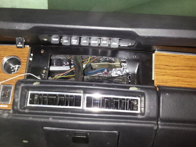
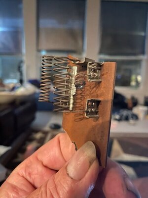
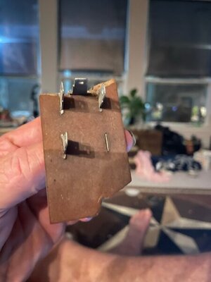
I have a 1970 Satellite with Factory air. The 2x previous owner had bypassed the blower motor resistor pack in favor of jumping a couple of the leads so the fan was either leaf-blower or off. The wiring connector housing was melted, and the resistor board was cracked, so I imagine he had some problems...

I immediately went to the Interwebz and found that nobody has a replacement. I decided to research Standard Motor Products' very nice searchable catalog. I looked for 4-pin units for Dodges, and just looked at the pictures. Unfortunately the physical dimensions and resistor values aren't listed, but I came up with a short list of possible units that had appeared to a) be generally rectangular in shape, b) have terminals that looked like they were compatible with standard-size spade lugs, and c) when cross-referenced to my local auto parts store, were in stock and not too expensive. My list was whittled down to about 5 possibilities.

My original unit, except for being cracked, was undamaged, so if I held it just right, I could get reliable resistance readings. Armed with my old unit (to match size) and my trusty Volt-Ohm meter, I toddled off to the auto part store to figure out the best fit.

Standard Motor Products part # RU109. If they make you look by make and model, say "1992 Jeep Grand Cherokee."

I bench-tested everything and determined the following wiring:
Tan wire to "L" (terminal on the new resistor pack)
Lt. Green to "M1"
Brown to "M2"
And the double dark-green to "H"
(I made a pigtail to a new harness so there's only one dark green wire shown)

Re-use the top 1/4" screw, and tighten snugly. It *just* covers the hole!
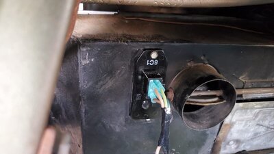
Blower Resistor.jpg
 
Hmmm...I have 3 resistors that I got in a parts stash.
Good that you found a way to make your car work.
 
Is there anyway you can measure the values of your old resistor pack? Starting at one end and between each tap. Another way may be to measure the current to the blower motor at full speed. With that value, you can compute the required resistance needed for each speed. The origional resistors are made from nichrome wire and are placed in the air stream for cooling, as they get very hot. Commercial wirewound resistors are a suitable replacement and are available. A third method maybe the inclusion of a GM variable speed control unit as used on their high level A/C platforms such as Yukon Denali and Cadillac Escalade. This unit used a current sinking power Darlington transistor to allow for variable speed operation without the use of high current high temperature resistor elements to provide the different blower motor speed voltages.
IF you could provide the total resistance values or total blower motor current draw, I may be able to calculate the resistance needed to provide stepped speed control. The fan laws dictate the amount of air flow produced at different speeds if the initial CFMs are known, and horsepower needed at each desired speed or volume delivered, backing into the current needed at each speed.
BOB RENTON

Yes. The resistance values are 2Ω for Low, 1Ω for Med, and 1/2Ω for High. Per my trusty Fluke 3000FC.

This resistor pack houses all the internal wiring in a large ceramic block about the size of a cigarette pack. Pretty good at heat dissipation.
 
I don't know for 70, but for 69 there is a mustang one that it is identical except one order is cut at an angle, like $12. Might not be the same deal.
 
71/74 B bodies got the max speed directly feed from A/C Control switch getting full power. Then the low and mid speed got the resistor. The 3rd resistor was used for heater speed, something between low and mid speed as far I recall... Shouldn't be like that on earliers ?
 
looking at diagram 68/69 diagram ( 70 maybe the same ? ), High speed is a straight feed from the switch not going through the resistor block, just like 71/74 are. Its spliced into the resistor block just to use that wire to source the output from resistor block to the blower with the speed selected using just one wire for the blower
69ACa1.jpg
.

On 71/74 Tan wire is low speed which is a default speed when turning on the system even with the blower switch disconnected going throught two resistors. Here could be the same. Light green is mid speed no matter if diagram shows low speed on switch, going throught just one resistor, Brown is Heater speed going throught 3 resistors. 68/70 seems to be a bit more complex on this due the time delay relay system.

I guess setting up Heater function, Tan wire power on 6 way plug is cut to feed the brown wire just to heater resistor series. Being cut the Tan wire, the Vent/AC blower speed switch and the block resistor stop to be sourced for these functions
 
Last edited:
to make it more graphic and JUST TALKING ABOUT THE SPEEDS selection outputs ( there is more involved about how the inputs are handled to switches but being simple as posible ) and how it runs the power to blower on each speed. Several splices around will spread out the power to several places, but the blower will be taking just what I'm showing ( per what I have analized )


this would be low speed. I guess on this speed the switch selector set on LOW SPEED should be cutting both low ( actually mid ) and high speeds outputs, just like setting it OFF, because if not, by Ohms law the resistor setup on mid speed and unexistant resistor on high, won't allow to select low.

69ACamid.jpg


This would be the mid speed

69ACalow.jpg


and this would be heater speed, a bit lower than Low Vent-AC low speed. On this setup the tan wire power from the 6 way block should be cut I guess

69ACaheat.jpg


High speed already shown on previous post
 
Last edited:
Well folks, I may have the wiring flipped a bit, then. It does work, but the fan speeds may not be right. At least I can swap the wires around a bit without much trouble.
 
I think is a bit more than flip out wires outside, but also some jumpers into the resistor setup inside? Dunno.
 
I think is a bit more than flip out wires outside, but also some jumpers into the resistor setup inside? Dunno.

Respectfully, no. I bench-tested (ok, my workbench is covered in crap, it was more like sitting-in-the-driveway-tested) with my Fluke 3000FC meter, the new M & H under-dash Heat/AC harness, the old harness, my original resistor pack, the new resistor pack, the blower motor, and the switches. [Actually, I only had the fan switch, not the vacuum switch assembly, it was melted into a ball of plastic when I got the car, and I had yet to order a new one from Summit.].

I also did not have the diagrams above. Thank you for those.

If it isn't too hot today, I'll be installing the vacuum switch and sussing out everything.
 
Speaking of the vacuum switch is there a vacuum canister or something in the engine compartment? or where does the vacuum for the system connect to on the engine? I'm reworking my heat/AC and the previous owner had removed a lot of it.
Sorry if I hijacked here.
Thanks.
 
Well folks, I may have the wiring flipped a bit, then. It does work, but the fan speeds may not be right. At least I can swap the wires around a bit without much trouble.

I'm curious if you figured out the correct placement of the wires for all the speeds to run in their proper order. I have been thinking there has to be a way to make your own resistor setup. I measured my resistor stamped 2837813 and found 2 ohms on low, 1 ohm on medium and 2.5 ohms on heater only.
 
Speaking of the vacuum switch is there a vacuum canister or something in the engine compartment? or where does the vacuum for the system connect to on the engine? I'm reworking my heat/AC and the previous owner had removed a lot of it.
Sorry if I hijacked here.
Thanks.
No vacuum reservoir used in the '72 A/C application.
 
This is the old original motor housing with the newer modern motor inside, the only visual difference are the two nuts, instead of the round carriage bolt type head. and of coarse the wires.
The next picture is of the rear a/c blower motor out of a conversion van .
20201130_145611.jpg
20201130_145753.jpg
I took my blower motor apart on my 69 charger. It wasn't working anyway. And installed a modern blower motor from the rear a/c unit of a conversion van. It fit in the original housing. The new blower motor has two shafts. So I cut one shaft off one side . To give the correct rotation that I needed . And it blows like crazy on high speed .the other two wires are medium and low speed. I had to fabricate a custom switch that now eliminates the resistor. I'll post some pics when I get home later. And the last picture is of the dash switch, which looks stock.. 20201130_145451.jpg
 
Last edited:
Hmmm...I have 3 resistors that I got in a parts stash.
Good that you found a way to make your car work.
My blower motor resister is shot on my 68 satellite convertible mine is broken in two a one of springs burned in 2 any help would be great

E988516F-F9CF-4D95-96C1-839B192E6064.jpeg CF0084B1-AED7-4888-B7A6-B128DF8821E0.jpeg
 
Auto Transport Service
Back
Top