• When you click on links to various merchants on this site and make a purchase, this can result in this site earning a commission. Affiliate programs and affiliations include, but are not limited to, the eBay Partner Network.

Degree an installed/unknown camshaft

Wietse

Well-Known Member
Local time
3:35 AM
Joined
Apr 16, 2017
Messages
2,164
Reaction score
1,022
Location
Netherlands
Hey guys,

In my '69 Coronet R/T i have a 440, which has been rebuild in the past but i have no specs about it.
The engine has a bit rough idle and low vacuum (10Hg) so i want to find out what camshaft specs it has in there.
By knowing the specs i might not find the exact part number (who knows it is a one-off grind) but i can hopefully determine the effective rpm range of this camshaft by comparing it with other camshafts with similar specs.
Current converter specs are also unknown, (someone advised met to do a check on the flash stall to get a close idea of the stall speed)
As i want to change my 4.10 ratio rear axle to a 3.23 or 3.55 ratio so i will have to consider all this to get a decent match for drivability. (cam, converter, rear axle ratio)

So, to do this i ordered a degree wheel and got a magnetic stand with digital dial gauge.
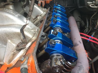
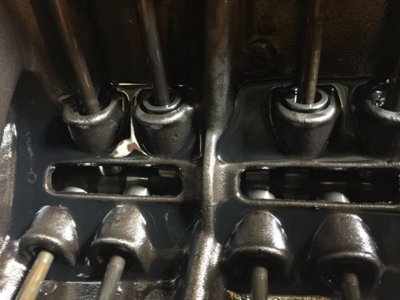
I know i have flat tappets, most likely hydraulic ones as i can see a circlip inside on de pushrod end. (maybe not, but hoping you guys know why the circlip is there, see pic)
There is no valve lash at all at any time, the push rods can be turned by fingers when the tappet is on the base line of the cam. (not loose, you need to apply a little force to rotate them)

I want to clear these things up first:
* Can i use the dial gauge and take the measurements on top of the rocker arm, right next to the adjustment screw of the push rod and confirm degree's and lift?
(setting it up in such a way that it is inline with the angle of the pushrod and in center of the adjustment screw)

* If they are hydraulic tappets, will they not cause a false reading when checking due to oil loss or so when they fight against the valve spring?

I am not sure about the rocker arm ratio (think 1.6) so to avoid a false reading due to incorrect ratio correction i want to avoid measuring on the valve spring retainer.
I don't want to pull any parts out because with my luck i am bound to **** something up, and there is no need for pulling parts out of this working engine.

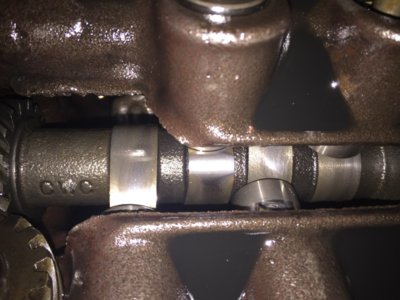
Regarding the camshaft, the only ID i found on the camshaft is CWC.
I traced it back and found this is Campbell, Wyant & Cannon, located in Muskegon, Michigan and they don't exist anymore under that name, now called Kautex, a Textron company.
And they manufacturer camshaft casts.
The do not do any grinding, just make the raw casts and sell them to the manufacturers who grind them to their own specs and sell them to the public.
It might be this is a one off grind done by a machinist who made a specific camshaft for a client, it could be as well that a company like Comp Cams or any other camshaft manufacturer use these as well, no idea.

Any thoughts and suggestions are welcome as always!!
Thx for reading!!
IMG_7829.JPG IMG_7823.JPG IMG_7758.JPG
 
you just about can't check much of anything at the valve or rocker with a hydraulic tappet; especially with a non-checking valve spring. you still have to find TDC and using a positive stop in the spark plug hole isn't perfect. you can find some information but accuracy will diminish quickly with the hydraulic tappet. if you use a solid tappet and a checking valve spring, and TDC is accurately located, then you should be good.
 
Thx lewtot,

I was in the understanding that TDC can be accurately found using a positive stop when letting the piston hit in both rotation directions, note the degree's and after hit for the middle of those figures.

So with hydraulic tappets i should remove the rocker shaft and remove the push rods on cylinder #1 to get the dial gauge installed directly in the center of the tappet.
But i am not sure if these are hydraulic tappets, i assume these are hydraulic as they have a circlip inside, and i believe the solid tappets don't have them. Also hydraulic tappets have preload and no valve lash right?
Yes, you can use piston stop as you've described to find TDC.
You might be able to indicate from the lifter if you remove a pushrod.
Normally we measure lobe lift by subtracting the width dimension from the height dimension.
Then multiply that number by 1.5 (or your particular rocker ratio) to define advertised valve lift.
If you can't pull the cam, you might get close enough by doing the indicate from lifter noting the smallest number while rotating engine and zeroing dial indicator. Then probably subtract the valve lash from the highest number indicated. Of course you still multiply that by your rocket ratio.
Check both an intake and exhaust lobe..
Using the degree wheel you can get close to the correct installation by understanding measured degrees between the intake and exhaust lobe split. In otherwords, find the highest lift on intake and note degrees. Find highest lift on exhaust and note degrees. The point in degrees opposite between is the split at zero lift... This should be TDC of crankshaft. If not, adjust accordingly.
 
a positive stop is not as accurate as an indicator on the piston. this might be splitting hairs for what you want to do. if you can find a stem extension long enough to reach the tappet, solid or hydraulic, that would take the rocker out of the equation. you will need to remove all plugs and if it were me i'd take the other 7 cylinders out of the process by not rotating the engine with the whole valve train hooked up.
 
Here's a picture that might help out regarding the previously mentioned methods..
lobecenters.jpg
 
Hey guys,

In my '69 Coronet R/T i have a 440, which has been rebuild in the past but i have no specs about it.
The engine has a bit rough idle and low vacuum (10Hg) so i want to find out what camshaft specs it has in there.
By knowing the specs i might not find the exact part number (who knows it is a one-off grind) but i can hopefully determine the effective rpm range of this camshaft by comparing it with other camshafts with similar specs.
Current converter specs are also unknown, (someone advised met to do a check on the flash stall to get a close idea of the stall speed)
As i want to change my 4.10 ratio rear axle to a 3.23 or 3.55 ratio so i will have to consider all this to get a decent match for drivability. (cam, converter, rear axle ratio)

So, to do this i ordered a degree wheel and got a magnetic stand with digital dial gauge.
I know i have flat tappets, most likely hydraulic ones as i can see a circlip inside on de pushrod end. (maybe not, but hoping you guys know why the circlip is there, see pic)
There is no valve lash at all at any time, the push rods can be turned by fingers when the tappet is on the base line of the cam. (not loose, you need to apply a little force to rotate them)

I want to clear these things up first:
* Can i use the dial gauge and take the measurements on top of the rocker arm, right next to the adjustment screw of the push rod and confirm degree's and lift?
(setting it up in such a way that it is inline with the angle of the pushrod and in center of the adjustment screw)

* If they are hydraulic tappets, will they not cause a false reading when checking due to oil loss or so when they fight against the valve spring?

I am not sure about the rocker arm ratio (think 1.6) so to avoid a false reading due to incorrect ratio correction i want to avoid measuring on the valve spring retainer.
I don't want to pull any parts out because with my luck i am bound to **** something up, and there is no need for pulling parts out of this working engine.

Regarding the camshaft, the only ID i found on the camshaft is CWC.
I traced it back and found this is Campbell, Wyant & Cannon, located in Muskegon, Michigan and they don't exist anymore under that name, now called Kautex, a Textron company.
And they manufacturer camshaft casts.
The do not do any grinding, just make the raw casts and sell them to the manufacturers who grind them to their own specs and sell them to the public.
It might be this is a one off grind done by a machinist who made a specific camshaft for a client, it could be as well that a company like Comp Cams or any other camshaft manufacturer use these as well, no idea.

Any thoughts and suggestions are welcome as always!!
Thx for reading!!
View attachment 795483 View attachment 795484 View attachment 795486

I located a post that included a nice write up / blank cam card you can use to fill in the data... This post goes into a bit more detail to include other data points as you degree your cam....

Quite useful info for those interested.

If you can get the cam card, then do so. If not, you can degree the cam without it.

Most cam cards have the following information. Without a cam card you must now fill in the blanks yourself. This is a lot easier than many think. If you have the necessary tools to degree a cam, you can generate your own cam card. It just takes a little more time and involves a small bit of math. The only thing you do not get when making your own cam card is recommended lash in the case of mechanical tappet cams and manufacturers desired Intake centerline. If you do not know the recommended Intake Centerline number then install the cam between 0* (straight up) and 2* advanced and you will be safe. Be sure to check clearances when installing a new camshaft or moving an existing cam.

--------------------------------------------------
CAM CARD

EXHAUST
Valve Opens at ______* BBDC
Centerline______* BTDC
Valve Closes at ______* ATDC
Duration ______ @ .050"
Lobe Lift ______ "
Valve Lift ______ "

INTAKE
Valve Open at ______* BTDC
Centerline______* ATDC
Valve Closes at ______* ABDC
Duration ______ @ .050"
Lobe Lift ______ "
Valve Lift ______ "

Lobe Seperation Angle ______ *
Valve Overlap ______ *
Cam Advance ______*

----------------------------------------------------

If I don't have a cam card I start with the exhaust lobe. I do this because any changes that need to be made are based off the Intake lobe and starting with the exhaust lobe means you don't have to move your dial indicator back over to the intake a second time if the cam is not in the correct location to start with.

First, Always
Degree Cam using the #1 Cylinder
Accurately locate TDC of #1 piston.
Make sure your degree wheel and pointer is secure and will not move during the entire process. If it moves even a tiny bit you MUST start the whole process over.
Always rotate the engine in the normal direction of travel. If you go past your desired measuring point, turn the engine back several degrees and come back on your measuring point in the normal rotation direction. This is to eliminate inaccurate numbers due to a loose timing chain.

Start with the Exhaust Lobe and measure the Exhaust centerline and fill in the blank.

Example: If your exhaust centerline measures 110* then write Exhaust Centerline _110_* on your card.

Now measure the Exhaust valve events. Rotate the engine so that the lifter rises .050" off the cam base circle. Write the number indicated on your degree wheel in Exhaust Valve Opens at _______. Then continue rotating the engine and note the dial indicator reading as the cam reaches maximum lift. Write this down in Exhaust Lobe Lift ________. Continue to rotate the engine and when the lifter returns to .050" write down the number indicated on your degree wheel in Exhaust Valve Closes _______.

Example: At .050" lifter rise the degree wheel pointer indicates 57* so write Exhaust Valve Opens at __57___. As the cam reaches maximum lobe lift the indicator reads .344" so write Exhaust Lobe Lift _.344_ " and finally when the lifter returns to .050 the degree wheel pointer indicates 20*, so write Exhaust Valve Closes at _20__*

Now we do a little math to figure cam duration and valve lift.

Take your opening and closing numbers and add them together and add 180 then write this number in Exhaust Duration ______ @ .050"

Example: 57 + 20 + 180 = 257
Exhaust Duration _257_* @ .050"

Take your Lobe lift and multiply by the rocker ratio or 1.6 in the case of a stock Olds engine and write that number in Valve Lift ______ "

Example: .344" x 1.6 = .550"
Exhaust Valve Lift _.550_ "

Now move your dial indicator over to the Intake lobe and repeat the process. Again I start with the Intake Centerline. Write this number in Intake Centerline______*

Example: If your Intake Centerline measures 108* then write Intake Centerline _108_* on your card.

Now measure the Intake valve events. Rotate the engine so that the lifter rises .050" off the cam base circle. Write the number indicated on your degree wheel in Intake Valve Opens at _______. Then continue rotating the engine and note the dial indicator reading as the cam reaches maximum lift. Write this down in Intake Lobe Lift ________. Continue to rotate the engine and when the lifter returns to .050" write down the number indicated on your degree wheel in Intake Valve Closes _______.

Example: At .050" lifter rise the degree wheel pointer indicates 14* so write Intake Valve Opens at __14___. As the cam reaches maximum lobe lift the indicator reads .348" so write Intake Lobe Lift _.348_ " and finally when the lifter returns to .050 the degree wheel pointer indicates 20*, so write Intake Valve Closes at _52__*

Now we do a little math again to figure cam duration and valve lift.

Again take your opening and closing numbers and add them together and add 180 then write this number in Intake Duration ______ @ .050"

Example: 14 + 52 + 180 = 246
Duration _246_* @ .050"

Take your Lobe lift and multiply by the rocker ratio or 1.6 in the case of a stock Olds engine and write that number in Valve Lift ______ "

Example: .348" x 1.6 = .556"
Valve Lift _.556_ "

Now to figure the Lobe Seperation Angle (LSA) take your Intake Centerline and Exhaust Centerline numbers and add them together and divide by 2. Write the result in Lobe Seperation Angle ______ *

Example: Intake Centerline measures 108 and the Exhaust Centerline measured 110 then (108 + 110) / 2 = 109
Lobe Seperation Angle _109_ *

To calculate valve overlap add the Intake Opening BTDC and the Exhaust Closing ATDC and writh the number in Valve Overlap ______ *

Example: Intake Opens at 14* BTDC and the Exhaust Closes at 20* ATDC. 14 + 20 = 34 or 34* Overlap
Valve Overlap _34_ *

To calculate Cam Advance subtract measured Intake Centerline from the Lobe Seperation Angle (LSA) If the Intake Centerline number is larger than the Lobe Seperation Angle then your cam is retarded.

Example: LSA is 109 so subtract measured Intake Centerline in this case 108. so 109 - 108 = 1
Cam Advance _1_*

If the LSA is 109 and the Intake Centerline were 109 then the cam would have 0* advance also known as "Straight up".

If the LSA is 109 and the Intake Centerline were 111* then the cam would be -2* retarded.


So, using the example numbers above your card now looks like this...
--------------------------------------------------
CAM CARD

EXHAUST
Valve Opens at _57_* BBDC
Centerline_110_* BTDC
Valve Closes at _20_* ATDC
Duration _257_* @ .050"
Lobe Lift _.344_ "
Valve Lift _.550_ "

INTAKE
Valve Open at _14_* BTDC
Centerline_108_* ATDC
Valve Closes at _52_* ABDC
Duration _246_ @ .050"
Lobe Lift _.348_ "
Valve Lift _.556_ "

Lobe Seperation Angle _109_ *
Valve Overlap _34_ *
Cam Advance _1_*


Read more: http://nitroimage.proboards.com/thread/2441/degree-cam-card-available#ixzz5sxDQOEu0
 
Thx for that very well described explanation 67 B-Body.
I will use that and follow to get all details.

I did look at several video's on youtube regarding how to degree a cam, but they all do it during engine building so heads not installed which is most accurate indeed by going from the piston with a dial gauge.

Regarding hydraulic lifters, do these also have a spring inside? And the oil pressure supports this spring by adding more cushioning effect or so?
So at rest the hydr. lifter is always fully "extended" with no valve spring pushing against it, even without oil pressure?

I am kinda scared of removing the rocker shaft, maybe will miss out on adjusting later on...
I've seen in these engine build video's when they adjust the rockers, they take away all lash and then add 1 more turn on the adjuster screw as pre-load on the lifter. (their lifters are new versus my used ones)
Is that what i should follow as well when installing the rocker shaft back on te engine?
Guess i could check by loosening a rocker adjustment nut and see how much i need to unscrew the adjuster before there is lash right? Making sure the lifter is on the base line of the camshaft.

It is not that i do not have technical back ground, but with jobs like this it would be sure and safe having someone guide you....i don't want to damage the engine obviously.

Edit: Yes for this job i guess i am better off removing both rocker arm shafts, spark plugs are out already.
 
Last edited:
Bu the time you go through all the task of checking the cam in the car your a couple of steps of yanking it out. It may have number stamped in it or replace it with something else you like. IMHO.
 
The plan is to remove the engine from the car for painting, (engine and engine bay), repairs and some other detailing and refurbishment.
Originally the plan started as i have a cracked header that will need repairs or replacement.

As mentioned before the manufacturer of the cam is CWC, which could mean it is a custom camshaft so there is a chance that it will not have any part numbers at all.
Bear in mind that 10-15 years ago this engine was rebuild the ease of getting parts from the US was not as easy as it is nowdays.
Therefore some machinist might have got the right camshaft cast and machined it according some specs
 
hydraulic tappets do have an internal spring, plunger, and check valve. the whole system relies on constant pressurized oil supply. take the supply away and the internals eventually collapse due to valve spring pressure.

CWC is probably the manufacturer of the cam core, not the grinder. most likely it's a shelf grind and not custom.

don't be afraid to remove the rocker assembly. you can carefully just re-install it without issue if you don't back off the adjusters.
 
Thx lewtot,
I was just wondering regarding the hydraulic tappet if it would leak down over time or i could accidentally push it in when checking cam specs but if there is a spring in there i am safe to assume it is "solid" when just working against a dial gauge.

So it would be no issue when removing the rocker shaft assembly as a whole, and without touching/adjusting anything i can install it back later on.
Nothing should change indeed, only thing i could think of if there are any shims under the rocker shaft.
Might need to keep an eye out for that, just in case there is some shimming done.

Hopefully i get my degree wheel this week, incl. the engine lifting plate and i can pull the engine out to do the needed work.
Probably end of next week i will have to go from home again as well for work...going to be tight..
 
i am safe to assume it is "solid" when just working against a dial gauge.
No. I'll go ahead, and post the hydraulic lifter/tappet drawing.
hydraulic-lifter-breakdown.gif


Note where the lifter pre-load is...there is a gap between the snap ring, and top of the cup/piston, however you want to call it.
Rule of thumb...for already broke in engines, never 'mix' lifters, from the cam lobes they have run on.

To dial in my cam, off #1 cylinder, I used a good old lifter, guts removed, and a 1/2" diameter steel rod cut to the length I wanted. Pressed that steel rod into the hollowed lifter, to make it solid. Took readings from the steel rod's end.
 
Thx Miller,

Now i understand how these type lifters are assembled.
I will not remove the lifters, they will stay inside so no chance to mix them.
So once the pre-load is removed the pushrod seat is pressed against the snap ring by the spring in the bottom.
That should be good enough to take a reading from with just a dial gauge right?
I don't have an spare/old lifters lying around so i have to do it with the one inside.
 
If you remove all the spark plugs, and the rocker arms the engine will (should) rotate over real easy. With the rocker arms off, you can align the indicator to the top of the pushrod (or use a really long indicator extension.)
https://www.amazon.com/gp/product/B005951CNA/ref=crt_ewc_img_dp_1?ie=UTF8&psc=1&smid=A2FYHGC4NSM6WF

For head on piston stop, I use the old Crane Cams (I think) single piece of threaded brass with a hole drilled through the center.
When I look up the part now, it is showing a two piece setup?.
Anyhow, the piston stop I have been using works pretty well, unless the engine has the real low compression pistons that sit far below deck at TDC.
The stock spark plug angle makes it difficult to contact the piston top because the angle go more across the bore than down into it.
If the engine has flat top pistons it should work, but if it has the low compression pistons that are 0.100+ below deck at TDC, it may be difficult to get the piston stop in that deep? Another idea may be removing a valve spring, and wrap some wire around the valve stem lock notch so the valve won't fall into the cylinder, and then measure when the piston hits/moves the valve?
 
Thx 451mopar,
I think i will get/make some support where the push rod can lay against in the cylinder head so it maintains a straight angle compared with the lifter.
Then install the dial gauge on the top of the push rod to take measurements.

I got a screw in piston stop, the adjustable bolt is quite long and should hit the piston.
I tried it before but the engine is hard to turn (and was difficult to put som muscle on it as the radiator and fan were still installed) so it was too hard to determine if it was against the stop or not.
The engine has 200 PSI cylinder pressure when doing a compression test so i don't think the pistons will be below the deck :D
 
That should be good enough to take a reading from with just a dial gauge right?
I'd say no. The 'hydraulics' of hydraulic lifters (oil/spring) works the movement of the piston, or cup, allowing a softer effect (from lack of words) on the parts. So, you could still get movement, push rod or directly on the lifter. Unless it was taken at the solid edge of the lifter.
Just so you know, especially with a cam like yours, the gap created with pre-load is, for one thing only. To not allow the top edge of the cup, to make contact with the retainer ring. If contact is made...how long do you think that retainer ring would last, with all that hammering?

There's different methods that could be used, to get the measurements your after, accurately. Of course, all mine was done, before heads went on.

Maybe just go with 1.5 rockers, and live with it?
 
Wel yeah, maybe aim for the edge.
But i will try, if i install a push rod, make sure it is not wiggling around and get the dial gauge and see if the lifter has any movement.
I don't think the weight of the push rod and the pressure of the dial gauge spring will be enough to compress it, but as i said i will confirm this before trying.
I want to get an as accurate possible reading in these circumstances.
But being a degree or 0.001" off on lift i could not bother.

Just so you know, especially with a cam like yours, the gap created with pre-load is, for one thing only. To not allow the top edge of the cup, to make contact with the retainer ring. If contact is made...how long do you think that retainer ring would last, with all that hammering?

Ok thx, yes that retainer ring would not survive very long in that case.
 
Do I understand this correctly, you're going to degree a cam with a hydraulic lifter and a push rod?

It will not work. Even if you think it works, your results will not be accurate enough, and you results incorrect.
 
Auto Transport Service
Back
Top