Wietse
Well-Known Member
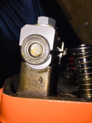
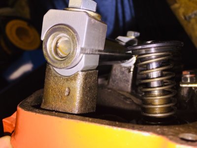
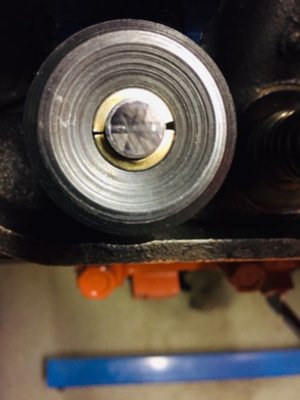
I am sure you have checked it but the roller looks like it could run of the valve stem at max valve opening.
I think that is going to be the last thing to happen with this B3 geometry kit.
I am sure you have checked it but the roller looks like it could run of the valve stem at max valve opening.
I have no idea who is the manufacturer of the rocker arms, from hear and say they are likely to be an MP product from several moons ago. (produced for MP by some known brand)
I don't know what would be the min/max adjuster setting.
I found a how-to on Hughes their website where they recommend a "base" setting of 0.300" and check max valve lift; after that you should increase/decrease the push rod length, compensate the adjuster screw and check again for max. valve lift.
Depending in which direction you get more lift, you need to keep playing in that direction until you find the push rod length where you find the highest valve lift.
This should indicate you have found the best geometry possible with that setup.
Makes sense in a way, but i don't know if i am giving up something else by obtaining the highest valve lift possible.
I mean, by getting the max valve lift i might put additional stresses on the rocker arm/adjuster screw and reduce life of these parts, or in a bad case scenario, break a rocker arm.
Here is the article:
http://www.hughesengines.com/Upload/productInstructions/HUG8220.pdf
I will have to do some final adjustments on the rocker arm shims to get them to sit straight above the valve stem and after i will remove the whole lot for another cleaning session before "final" assembly.
After that i will start fingering with the adjustable push rod and see what i get.
I am not sure about the process of adjusting for maximum lift? I think the maximum lift adjustment would end up with the adjuster straight in-line with the pushrod at max cam lobe lift? I think it really depends how much angle the adjuster part of the rocker has, and your cam lift.
Learn something new all the time
I was thinking the pushrod would change the adjuster distence out which would change things if the adjuster was not in line with the pushrod at half lift
many rockers do not have the adjuster at the correct angle for a mopar which i do know
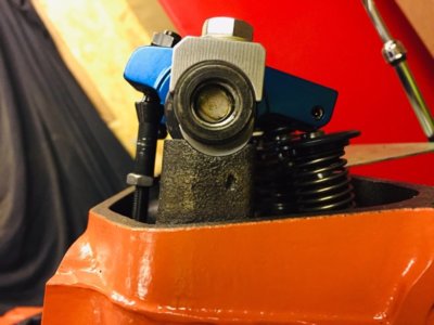
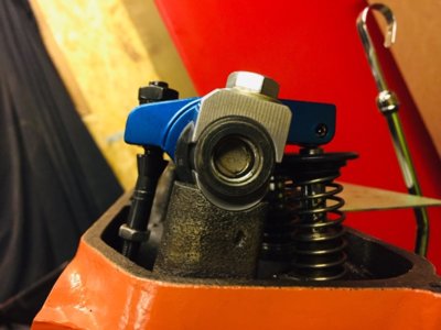
I just think saying the stock geometry is f* up is an overstatement, it just is not correct for your application.
It's not really because the higher lift that makes the rocker shaft to be raised, it is required when using a roller rocker arm just by itself. As the pivot point moves upwards because of the roller tip, the rocker shaft needs to come along with it.Not sure how raising the rocker helps geometry when using a higher lift cam. I thought the rocker is supposed to be perpendicular to the valve at mid lift?
Great If I find the time I’ll read all of themVery true about getting the TDC position right.
But that task was done a few pages back, i am already finalizing valve train components
451
it's the addition of the .250 radius of the roller that's the problem
you want the center of the rocker fulcrum/ shaft and the roller to be perpendicular at half lift which is why you have to raise the fulcrum, otherwise you start with the rocker tilted up and you can see what happens at half lift and full lift
also the acceleration is greater toward full lift when the cam is trying to slow down the valve going over the nose so you have to use stronger springs and can float the valve easier
