• When you click on links to various merchants on this site and make a purchase, this can result in this site earning a commission. Affiliate programs and affiliations include, but are not limited to, the eBay Partner Network.

Frnknsteens '69 Charger project

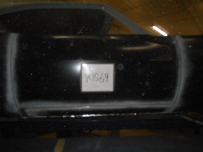
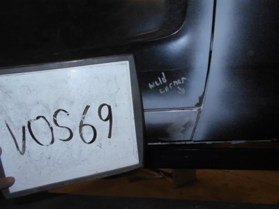
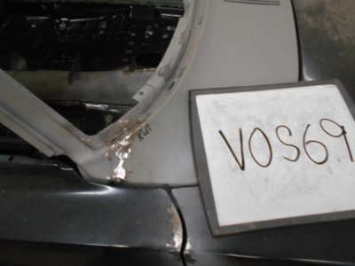
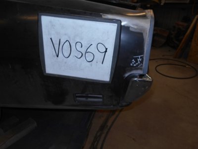
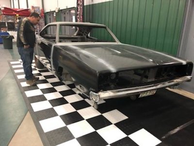
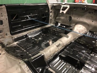
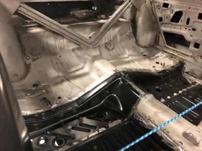
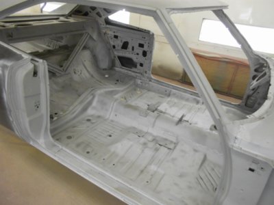
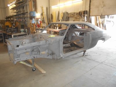
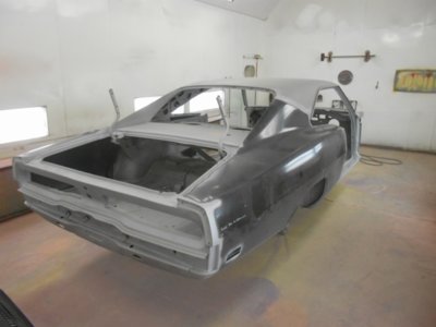
It's official!! Metal work is DONE!!

I was told they will be bringing the Charger to the Toppers Car Show in Fargo North Dakota in two weeks to put on display to show the work they do, then it will go to prep and paint. So if any of you live up in the Fargo North Dakota area and plan to go to that show,... Let me know how it looks!! :thumbsup:

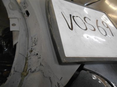
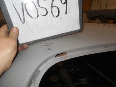
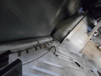
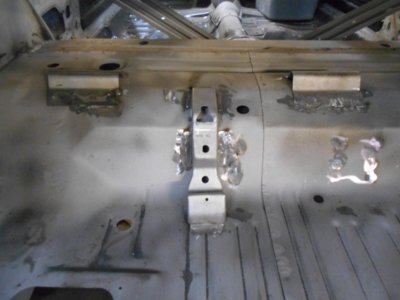
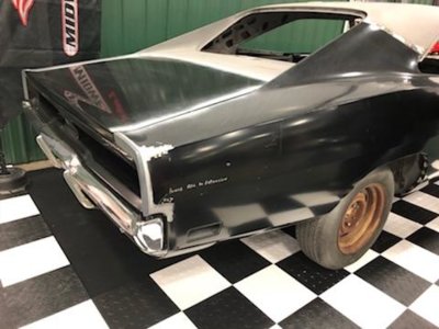
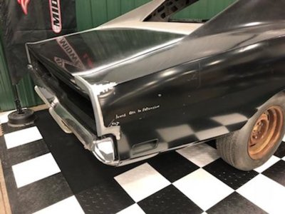
Final work that was done was to fix some miscellaneous bad spots and weld in the spare tire and jack brackets. Can't tell you all how fun it is to see the body of this car all back in one piece.

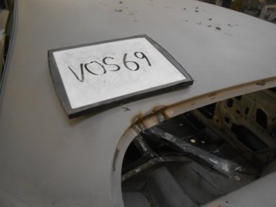
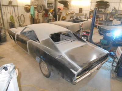
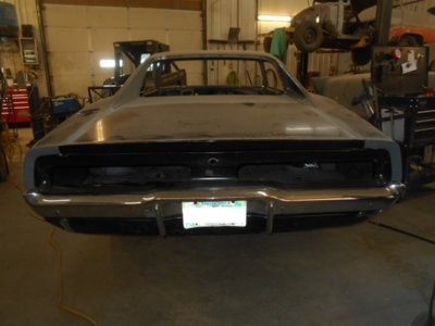
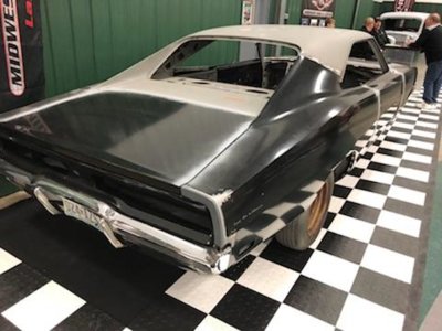
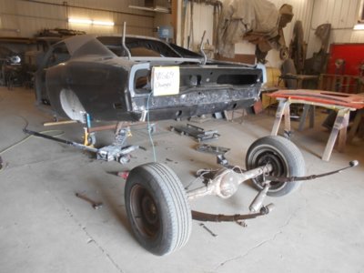
My hope is to get my motor done and bring all the parts up there in time to see the paint go on. I know it may sound silly, but after all these years, I really want to be there when it is painted and see the color go on! Pics I'm attaching are the final areas they addressed and a couple shots of the whole car now that metal work is done.

I never realized how sexy the butt on these cars are until I saw the last picture!!:lol:

DSCN2461 (640x480).jpg DSCN2487 (640x480).jpg DSCN2488 (640x480).jpg DSCN2508 (640x480).jpg DSCN2509 (640x480).jpg
 
Last edited:
Oh man, you must be excited to see the metal done....I know I am. Great car and cannot wait to see body work, primer and paint!
 
Oh man, you must be excited to see the metal done....I know I am. Great car and cannot wait to see body work, primer and paint!

Can't tell you how excited I am right now! I'm hoping body work goes quickly! Don't get me wrong, I want it done right, but it wouldn't hurt my feelings to see less than expected hours for that since metal work was more than expected! :eek:
 
So I had been told that the shop doing my car was planning to take it to the Toppers car show in Fargo ND this weekend. I have a friend living in Fargo that remembers riding in this car with me when we were young. I had called him and told him the Charger was supposed to be at the show this weekend. He went to the show with his family and called me from the show saying how much seeing that thing brought back memories. He took some pictures of it and sent them.

The car is scheduled to go into prep and paint after they get it back to the shop.

7064.jpeg 7068.jpeg 7071.jpeg 7073.jpeg 7076.jpeg 7077.jpeg
 
Started going through my instrument cluster today. I know there are companies out there that do that, but it is a little mind numbing what some of those companies want to do it. I am getting older, and want this project done so I can enjoy the car, but I just can't afford to pay others to do everything so I am doing what I can myself. I found a good thread on another forum site that walks you through restoring the instrument cluster, so I am giving it a shot. I didn't think to take pictures while pulling it apart (Typical of me), but I did start taking pictures of it going back together. I ordered resistors and a DC power supply today to test the gauges to see which ones work before re-doing the faces, so those are on hold for now, but started with the assembly housing first.

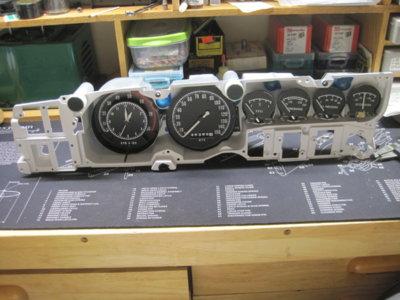
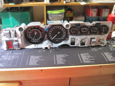
I started by removing everything out of the housing and bagging each item. Then I went through all those items and cleaned/inspected the chrome and tested the switches and everything seems to work. The two switches that confused me a little were the headlight switch and the wiper switch. I need to see which posts are for what so I can confirm I have good continuity through everything. On the ones that made sense, I broke them down and cleaned all the contacts and put a touch of dialectric grease on the contacts.

I have two assemblies, so I pulled everything out of both of them, only to find out that one of them was bent, so I am using the good one. Turns out my instrument clusters were an early '69 ( the one that was originally in the car) and a late '69 or '70. From what I have read, the dimmer assembly housings are different. My early '69 dimmer was rough, and the later model was better, so I disassembled and cleaned the later one to make sure I had one that worked. I will try to restore the early model one, as I prefer to use that one since it was the one that came out of my car.

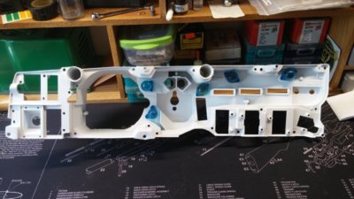
Last step of disassembly was to remove the blue lenses, which was done by heating the tabs with a soldering gun, carefully blipping the trigger so it didn't get too hot and vaporize the plastic tabs. A little pressure on the lenses while heating and they slid out, leaving a little hoop of lens material. I saved those little pieces to re-melt back in when reassembling.

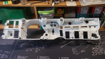
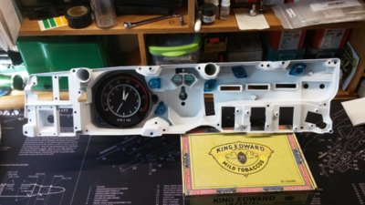
Pictures below are of the cleaned and painted housing, the blue lenses cleaned and re-installed, and a new OER clock/tach installed. Next will be to carefully remove the speedo face and reface it using decals I found through Performance Car Graphics.

0407181545_HDR.jpg 0407181611.jpg 0407181618.jpg
 
Last edited:
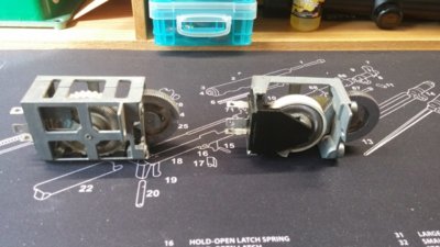
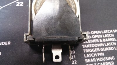
Below is a picture of the two different styles of Dimmer assemblies. The one on the left is the early model, and the right is the later model. The early model is a full cage and seems more robust. It is held together with a couple rivets. On the later model, the inner wheel assembly slides into the outer case and is staked in place.

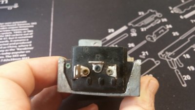
Since the later model worked, for the most part, I started with it. Testing it with an ohm meter, I was able to watch the ohms change when the wheel was turned. I had to do a little reading to learn how it worked. There are three spade terminals on the switch. One for power, marked "I" for Input, One marked "R" for Resistance, and one marked "D" for Dome. According to my reading, the resistance should range from 0 to 20 ohms when you turn the dimmer wheel (20 ohms for low light, and 0 ohms for full brightness). When clicked into position for the Dome light, the "D" terminal is supposed to ground to the case and provide ground to the dome light. Mine gave me sporadic ohms readings as I turned the wheel, and didn't ground to the case when the dome light was clicked on.

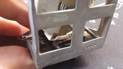
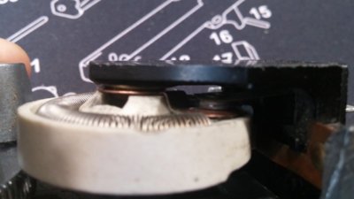
I was able to carefully open the stakes so the black inner assembly could slide out. I could then carefully take the wheel out and clean the resistor spring and the contact point. There is a raised portion on the wheel that presses a thin copper arm against the case to ground it out and turn on the dome light (See third picture). I had to clean that copper spring, and the case where it contacted it as well. Once everything was clean, I reassembled the dimmer switch and tested it. Putting an ohm meter across the "I" and "R" terminals, and turning the dimmer wheel gave me a clean ohm range of 19.8 ohms through 0 ohms with no dead spots. (FYI,... There is a copper pad at the end of the spring. When the contactor moves up off the spring onto that pad, ohms should be at "0" (See last picture). When the contactor is at the other end of the spring, it should read about 20ohms). I then set the meter to continuity and connected one end to the "D" terminal and the other to the case. I rolled the wheel up into the dome position and the continuity alarm went off every time I clicked it into position and turned off when I rolled the dome light off. Success!!

I lightly squeezed the case in my small vice and staked the ends on the channel back down, capturing the roller assembly back into the case(4th picture). I retested ohms of the roller wheel, and tested continuity to the case in the Dome light position and everything is working fine. One switch down!

0408181654.jpg 0408181717.jpg 0408181718.jpg 0408181718a.jpg 0408181719.jpg
 
I like that you are restoring the instrument panel yourself. I did not feel confident enough in myself at the time so I sent mine off and had it done. May be if I had step by step instructions I could have done it.
Keep up the good work.
 
I like that you are restoring the instrument panel yourself. I did not feel confident enough in myself at the time so I sent mine off and had it done. May be if I had step by step instructions I could have done it.
Keep up the good work.

Thanks showard. Don't get me wrong. It's a little intimidating. I ordered a DC power supply to be able to put 5volts to the gauges. I'm just waiting for the 10ohm, 23ohm, and 75ohm resistors to be delivered so I can start testing the gauges. Once I know which ones work, I will drill out the rivets, bead blast the faces, paint them and apply the new face decals.

The speedometer has me a little intimidated. I have no worries about taking the face off and refinishing it. My concern is if there is enough wear on it that it warrants sending to someone to have them rebuild it. I took a look at it and it is a maze of worm gears running the speedo and the odometer. I'm debating refinishing it and then sending it to someone to have them go through the bearings/bushing to make sure it is good to go.

To be honest, since there is nothing in there but bearings, bushings and gears, I thought about dunking the whole thing (minus the odometer) in my fishing reel solution, then re-oiling the bearings/bushings and re-greasing the gears like I do my baitcasting reels for fishing. Not much difference if you really think about it. :)
 
Last edited:
Wow,... Life got me sidetracked for a little while. Had to get some parts blasted and repainted to be ready for the engine to be finished. Back to the instrument cluster tonight.

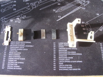
Checked the rest of the switches with an ohm meter and a continuity tester and all are working good, with the exception of the vacuum switch for the headlight doors. It was shot, but they are WAY more expensive than I thought, so I'm going to try to fix it. There really isn't much too it, from what I've seen online. Just a grooved rubber block, a backer plate and a bent piece of spring steel to keep it seated and sealed. I cut the plastic heads for the pins off to be able open it up. I will drill it and put it back together with small flathead screws.

Once it is apart, I confirmed how it works, as shown in the pictures below. I need to get some small flathead screws. I bent the spring a little to give it a little more pressure, and plan to lube it up with a little lithium grease as I put it back together. I'll get back to that once I have the screws I need. For now, the picture below shows all the components laid out in the order they are in the switch.

IMG_1227.JPG
 
Since I can reattach that once I get it back together, I decided to start reassembling the Instrument cluster. After testing all the gauges and confirming they all worked, I drilled out the rivets to remove the faces of all four gauges and the speedometer. As I showed above, I bought an OER Tic Tock Tach, and already had it installed.

Once all the faces were removed, I bead blasted them to remove the old paint, faded lettering, and beginnings of rust. I will warn you that the face on the Ammeter gauge is aluminum instead of steel like the rest. Be careful when stripping it, because I bent the heck out of it bead blasting it, but I was able to save it. Once cleaned, I painted them with satin black (I used Rustoleum satin). The decals I bought from Performance Car Graphics had a satin sheen to them, so flat or gloss would not match up properly and you'd see the edges of the decals. The needles on mine were still good and white, so I didn't paint them. I didn't trust myself renumbering the odometer, so I sent it to Performance Car Graphics after I had applied the decals and reattached the face. They renumbered the odometer, and gave the speedo a good cleaning and relube. Not bad..., they charged me $45 for the clean & relube and 30 to renumber the odometer and paint the needle (it matches up nicely with all the others) and had it back to me within a week.

Time to start remounting them back in the cluster housing:

IMG_1221.JPG
 
I will remind you now, before you go any further if you are doing this yourself. Make sure you re-installed the red hi-beam indicator lens that sits behind the speedometer. Ask me how I know to remind you,... Yep! I had it all back together when I realized I hadn't put it in. I had to pull the Bezel back off, remove the lens assembly, remove the speedometer, install the red lens for the hi-beam, then put it all back together again.

Next came putting in the green turn signal lenses and seals and the Brake System lens and seal. Performance Car Graphics sells those too. The Brake System lens decal is just a clear decal, so you have to wet sand your old red lens back smooth and get all the old lettering off. I started with 800 grit and water on a cutting board to keep it flat and true. Then I worked my way up through 1000, 1200, 1500, and 2000 grits wet-sanding papers to make sure I didn't have any sanding marks. I happened to have them from when I refinished a guitar and had to sand out the lacquer finish before polishing. If you didn't have all those, I would get ahold of some 600 grit and 1000 grit and wet-sand with those. Once you have the red Brake System lens clean and smooth, spray both the lens and the decal with glass cleaner and apply the decal and slide it into its proper alignment. Then squeegee out the air bubbles and you are done.

Next step was to re-install all the switches. Hind-sight being 20/20. Put them in, but leave the screws a bit loose. You will have to tweak them a bit when you mount the bezel to center them in the opening as best you can, so no need to tighten them down completely right away.

EDIT,... Just noticed the right turn signal lens had fallen off in this picture. It did that a lot!! I would suggest not putting them on until right before you mount the bezel.

IMG_1224.JPG
 
I just noticed a couple things I didn't discuss, or forgot to take pictures of. Before you get ready to mount your bezel (and lens), or if you haven't started any of this yet. Once you paint your housing white on the inside, there are mounting holes that the screws go through to attach it to the dash. You will want to paint a little black around them, or the white paint will show around the mounting screws. The easiest way to know which ones is to lay your bezel over the housing and see which holes will show. For now I can tell you it is the hole above the oil pressure gauge, the one between the tach and speedo on top, and the far bottom left hole, but I think the far bottom right needs it too. Lay the bezel on it, and just do them all.

The other thing is I noticed is I didn't take a picture of the lens assembly going back on. It just attaches with little spring clip/pins. I took them off carefully from the back by carefully squeezing them with a needle nose pliers. Give them a light little squeeze and they pop right out. Reattach the lens assembly by just popping them back into place. Once the lens assembly is back in, you can reattach the bezel. A piece of advice,.... remember to check and make sure you have your turn signal lenses and seals in place and that the seal doesn't show through the hole in the bezel. Other than that, go slow and try to keep the mounting holes for the dash as best aligned with the bezel holes as you can as you tighten the bezel screws from the back. Once everything is tight, tweak all your switches to align them to the openings and tighten them down.

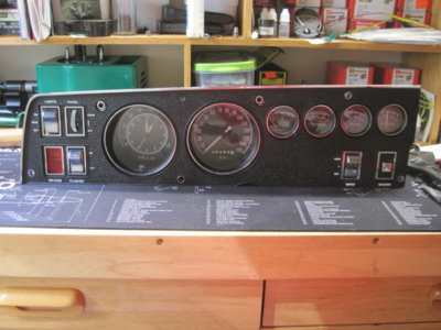
Done!!! All I have to do now is finish redoing my vacuum switch for my headlight doors, and reattach it to the headlight switch from the back and I will be done. It may not be perfect, but I honestly don't see any issues with it. And I saved most of the $1500 - $2000 that some of the companies quoted me. Instead, I bought a new repopped bezel kit and the OER Clock Tach.

EDIT,.... In this picture, you can see what I was talking about when I said the white will show through the mounting holes (One on bottom left, On below tach and speedo, and one above the oil pressure gauge). I painted those while I had it back apart to put the hi-beam lens in. This picture was taken after completing it the first time before pulling it apart to fix the missing lens. The other two (Turn signals 10:00 to tach and 2:00 to speedo are the chrome trimmed turn signal indicators).

IMG_1226.JPG
 
Just got an email that the shop working on my car has completed prep to be moved into the paint shop. They removed the rear suspension, did the final blasting, mounted it on the rear jig and moved it into the paint shop to start the fill and prime process. Pictures I got are included below.

DSCN0981 (640x480).jpg DSCN0989 (640x480).jpg DSCN0984 (640x480).jpg DSCN0987 (640x480).jpg
 
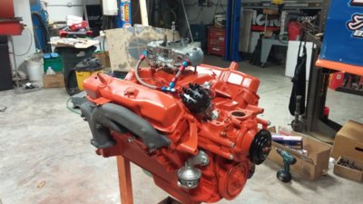
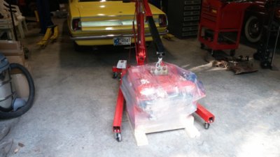
Well,... Another big chunk completed on the build. I received the motor back from the engine shop yesterday. I don't have all the specs with me here right now, but it is a .030" over 440. Sealed Power forged pistons. They calculated the compression ratio and said it will be sitting at about 9.7:1 compression. Cam is an Erson Cam with slightly over stock duration and larger lift. We went with 1.5 ratio roller rockers and new rocker shafts. The engine guy is getting all the part numbers together for me so I will have all the specifics, but I'm just excited to see another milestone met.

0531180935.jpg 0531181921.jpg
 
Looking Good!
Hopefully the paint is coming along good too.
 
Looking Good!
Hopefully the paint is coming along good too.

Haven't heard anything on the paint work yet, and haven't gotten any new invoices. I think it is in queue and waiting for cars ahead of it to be completed. That works for me thought because I am getting as many parts ready as I can. My hope is to time it out correctly to be able to bring them up there around the time they are getting ready to lay the paint down. For some reason I really want to be there to see the color go on.
 
Auto Transport Service
Back
Top