• When you click on links to various merchants on this site and make a purchase, this can result in this site earning a commission. Affiliate programs and affiliations include, but are not limited to, the eBay Partner Network.

no spark - coil

Ok, turning over is the 'start' position. So you have jsut over 9V at the ballast resistor in the start position. I think that's wrong, right guys? In the start position, the brown should bypass the ballast resistor and deliver a full 12+ V to the coil. In the run position, the blue tracer feeds through the ballast and should deliver the reduced voltage to the coil. sounds like maybe the ballast resistor is hooked up wrong. Sounds like the two ignition leads might be reveresed on the resistor.
 
Try unplugging the ECU 5-pin connector and test both wires going from the magnetic pickup connector to the ECU - you should get something like 0.03 ohms. Maybe a wire has been cut/crushed or melted. It is starting to sound like a back-feed from your alternator. Pictures of the areas might be useful to prevent all this 'stabbing in the dark'.
 
Ok, turning over is the 'start' position. So you have jsut over 9V at the ballast resistor in the start position. I think that's wrong, right guys? In the start position, the brown should bypass the ballast resistor and deliver a full 12+ V to the coil. In the run position, the blue tracer feeds through the ballast and should deliver the reduced voltage to the coil. sounds like maybe the ballast resistor is hooked up wrong. Sounds like the two ignition leads might be reveresed on the resistor.
yes it sounds like the wiring is backwards with the two ignition circuits.check a wiring diagram to get it right,may not be as simple as backwards on resitor.
 
should be a bit above 12 in and about 9 volts out.may indicate a wiring issue.what is the voltage of your battery?needs to be above 12.6 to test electrical.

battery is 12.61
 
It doesn't matter which way around the wires are on the resistor - as long as the START + RUN are not on the same side. Resistors are made to go either way.
 
Try unplugging the ECU 5-pin connector and test both wires going from the magnetic pickup connector to the ECU - you should get something like 0.03 ohms. Maybe a wire has been cut/crushed or melted. It is starting to sound like a back-feed from your alternator. Pictures of the areas might be useful to prevent all this 'stabbing in the dark'.

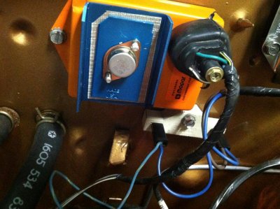
coil.jpgcontrol unit.jpgignition unit.jpg
 
Help. Still at a stand still. Happened to have another coil, tried that NG. Even tried a new ballast resistor, NG as well. I am at a lose when it comes to electrical. I have 11.70 on 1 side of the ballast resistor but only 7.3 on the other. The coil wire only has 7.3 as well. The other side of the coil only has .6 when I crank it over still only 7.3 on the one side but the other side does go up to 1. Not surre what's next. I wish I knew a good mechanic by me and I would have them fix it ASAP. Any thoughts, PLEASE...
 
When you crank it the ballast resistor should be bypassed and you should have a full 12 volts at the coil.
The ballast bypassing 12V directly to the coil cames from the ignition switch.

The 11.70 volts is low, you should have very close to full battery voltage at one side of the ballast resistor. The 7.3 after the ballast to the coil is about normal.

When I crank it the voltage does not change, it stays low. Any ideas?
 
Did you check the gap/clearance on the magnetic pickup inside the distributor. This is the "trigger or pulse" that the ECU is looking for to fire the coil. The coil can have voltage on it, but won't fire until told to. Check continuity (smallest ohms scale) on your multimeter, and see that the 2-pin plug from the distributor to your corresponding wires on the ECU socket are good. I know they look new, but you have to check all this stuff to be sure. Make sure when you plug the distributor back with the ECU loom, there is a good solid fit.
My suspicions rest with the magnetic pickup or ECU, if everything else is good as you say.
I had this sort of grief a few months back, and I also trawled through the FABO site for suggestions & clues.

67Dart273 gives good info;

http://www.forabodiesonly.com/mopar/showthread.php?t=157583&highlight=car+cranks+start


hope that helps a bit
 
HI. A list of several things to go through, not necessarily all detailed to the present conversation

1--Very first job is to make ABSOLUTELY sure that the box is grounded.

2--Your voltage readings on neg side of coil seem to indicate that the box is not switching. Might not be grounded, might be a bad box, or MIGHT BE a FIVE PIN BOX

You cannot always tell a 4 pin box from a 5, as "some" replacement boxes have 5 pins, but only 4 are hooked up. Since you are using a 2 pin ballast, you may have the opposite problem --you may have inadvertenly gotten an older, 5 pin box

A 5 pin box MUST have a 4 pin resistor. Only way to tell on a box with 5 physical pins is to "ohm out" the 5th pin and decide if it's hooked to anything.

A newer, 4 pin box CAN use either a 2 or 4 pin resistor.

Understand that the Mopar ECU basically replaces points so that means that it SWITCHES the neg side of the coil to ground. Normally, with key on, the coil voltage would be fairly low, IE several volts below the coil + reading

====================================================================

3--In addition to above, check that the box is getting power. You might need to use a straight pin and penetrate the box connector so that you can measure voltage under "real conditions." Assuming this is a 4 pin box, this diagram:


Ignition_System_4pin.jpg


From the above diagram, the far right "existing wire" represents the power coming in from the ignition switch. Notice that it goes to the ballast, and also branches off down to the box. Penetrate that plug terminal with a pin so that you can check voltage AT THAT PIN with the key in "run" and everything hooked up. You should read battery voltage.

4--In that diagram what is NOT shown is the brown, which comes from a separate contact on the ignition switch, through the bulkhead, and to the coil+ side of the ballast THIS WIRE is the ONLY source of ignition voltage in "start" With your meter on the coil+ and "cranking" USING THE KEY and NOT by jumpering the start relay, coil + should read "same as battery" and in no case less than 10V

=======================================================

5--Also, check your reluctor gap at .008" (inches, not metric) with a brass feeler. Last I knew O'Really had 'em

6--You can get some idea of distributor condition by setting your meter to "low AC volts" and hook the leads to the two terminals of the distributor connector. Crank the engine. The distributor should generate about 1V AC

7--In general realize that "new" parts can be defective, whatever the part

8--Your voltages seem low. This would be a good time to check for voltage drop in the igntion harness. I already touched on one check in (4) above. Let's do that in a different manner this time. Clip your meter to coil +, and the other lead to battery + the stud on the starter relay is good. Set the meter to low DC volts. Crank the engine USING THE KEY, and as the engine cranks read the meter. You are hoping to read a very LOW voltage here, as you are reading voltage drop across the harness. If the reading is above .3V, you have a "voltage drop" problem and need to look into this

9--Let's check the "run" circuit the same way. Now hook your meter to an "ignition run" line, (IGN 1) such as the blue alternator field wire, or the "key" side of the ballast --the side which goes to the bulkhead. Hook the other meter lead to battery +. Turn the key to "run" with engine off. Once again, you are hoping for a very low reading, and more than .3V (three tenths of one volt) you have a harness drop problem

The original circuit goes in this path:

Battyer -- starter relay stud -- fuse link -- bulkhead connector -- ammeter circuit -- in harness splice -- ignition switch connector -- through the switch -- back out the switch on dark blue "ignition run" -- back through the bulkhead -- and to the underhood loads.

On 69/ earlier, the above feeds ignition and the regulator IGN terminal

On 70 / later the above adds alternator field (blue), electric choke and idle solenoid if used, and distributor retard if used, and one or two other smog doo dads on some cars.

The most common REASONS for voltage drop in this circuit is -- poor connections in the bulkhead connector, in the ignition switch connector, in the switch, sometimes the ammeter connections or the meter itself, and in very rare but has happened, failure in the factory welded splice. This is a splice in the black ammeter wire under the dash, a few inches into the harness up by the cluster. If further checking should show that might be, you'd have to pull the cluster and untape the harness from the ammeter until you find it.

PLEASE read the always excellent MAD article on ammeters. Even if you do not (now or ever) perform this mod, it points out the hows and whys of what happens with these old girls.

http://www.madelectrical.com/electricaltech/amp-gauges.shtml

The simplified diagram down the above page shows the main power dist. in these cars. What they left off was through the ign switch and back out the bulkhead

amp-ga18.jpg


By the way, my all time favorite car was my old 440-6 70 RR. If I could afford it I'd have more than one

http://moparforums.com/forums/f62/my-old-ride-back-day-596/

I have no good photos anymore

81sruds.jpg


The car before I owned it, George, my friend and original owner, had just trophied in pure stock, probably at Lions

attachment.jpg


Ya. Me. When I was a young little SOB
attachment.jpg
 
HI. A list of several things to go through, not necessarily all detailed to the present conversation

1--Very first job is to make ABSOLUTELY sure that the box is grounded.

2--Your voltage readings on neg side of coil seem to indicate that the box is not switching. Might not be grounded, might be a bad box, or MIGHT BE a FIVE PIN BOX

You cannot always tell a 4 pin box from a 5, as "some" replacement boxes have 5 pins, but only 4 are hooked up. Since you are using a 2 pin ballast, you may have the opposite problem --you may have inadvertenly gotten an older, 5 pin box

A 5 pin box MUST have a 4 pin resistor. Only way to tell on a box with 5 physical pins is to "ohm out" the 5th pin and decide if it's hooked to anything.

A newer, 4 pin box CAN use either a 2 or 4 pin resistor.

Understand that the Mopar ECU basically replaces points so that means that it SWITCHES the neg side of the coil to ground. Normally, with key on, the coil voltage would be fairly low, IE several volts below the coil + reading

====================================================================

3--In addition to above, check that the box is getting power. You might need to use a straight pin and penetrate the box connector so that you can measure voltage under "real conditions." Assuming this is a 4 pin box, this diagram:


Ignition_System_4pin.jpg


From the above diagram, the far right "existing wire" represents the power coming in from the ignition switch. Notice that it goes to the ballast, and also branches off down to the box. Penetrate that plug terminal with a pin so that you can check voltage AT THAT PIN with the key in "run" and everything hooked up. You should read battery voltage.

4--In that diagram what is NOT shown is the brown, which comes from a separate contact on the ignition switch, through the bulkhead, and to the coil+ side of the ballast THIS WIRE is the ONLY source of ignition voltage in "start" With your meter on the coil+ and "cranking" USING THE KEY and NOT by jumpering the start relay, coil + should read "same as battery" and in no case less than 10V

=======================================================

5--Also, check your reluctor gap at .008" (inches, not metric) with a brass feeler. Last I knew O'Really had 'em

6--You can get some idea of distributor condition by setting your meter to "low AC volts" and hook the leads to the two terminals of the distributor connector. Crank the engine. The distributor should generate about 1V AC

7--In general realize that "new" parts can be defective, whatever the part

8--Your voltages seem low. This would be a good time to check for voltage drop in the igntion harness. I already touched on one check in (4) above. Let's do that in a different manner this time. Clip your meter to coil +, and the other lead to battery + the stud on the starter relay is good. Set the meter to low DC volts. Crank the engine USING THE KEY, and as the engine cranks read the meter. You are hoping to read a very LOW voltage here, as you are reading voltage drop across the harness. If the reading is above .3V, you have a "voltage drop" problem and need to look into this

9--Let's check the "run" circuit the same way. Now hook your meter to an "ignition run" line, (IGN 1) such as the blue alternator field wire, or the "key" side of the ballast --the side which goes to the bulkhead. Hook the other meter lead to battery +. Turn the key to "run" with engine off. Once again, you are hoping for a very low reading, and more than .3V (three tenths of one volt) you have a harness drop problem

The original circuit goes in this path:

Battyer -- starter relay stud -- fuse link -- bulkhead connector -- ammeter circuit -- in harness splice -- ignition switch connector -- through the switch -- back out the switch on dark blue "ignition run" -- back through the bulkhead -- and to the underhood loads.

On 69/ earlier, the above feeds ignition and the regulator IGN terminal

On 70 / later the above adds alternator field (blue), electric choke and idle solenoid if used, and distributor retard if used, and one or two other smog doo dads on some cars.

The most common REASONS for voltage drop in this circuit is -- poor connections in the bulkhead connector, in the ignition switch connector, in the switch, sometimes the ammeter connections or the meter itself, and in very rare but has happened, failure in the factory welded splice. This is a splice in the black ammeter wire under the dash, a few inches into the harness up by the cluster. If further checking should show that might be, you'd have to pull the cluster and untape the harness from the ammeter until you find it.

PLEASE read the always excellent MAD article on ammeters. Even if you do not (now or ever) perform this mod, it points out the hows and whys of what happens with these old girls.

http://www.madelectrical.com/electricaltech/amp-gauges.shtml

The simplified diagram down the above page shows the main power dist. in these cars. What they left off was through the ign switch and back out the bulkhead

amp-ga18.jpg


By the way, my all time favorite car was my old 440-6 70 RR. If I could afford it I'd have more than one

http://moparforums.com/forums/f62/my-old-ride-back-day-596/

I have no good photos anymore

81sruds.jpg


The car before I owned it, George, my friend and original owner, had just trophied in pure stock, probably at Lions

attachment.jpg


Ya. Me. When I was a young little SOB
attachment.jpg

1st off; cool RR. My buddy had a 70 plum crazy with white interior 440 6 pack pistol grip RR when I growing up. Since then i always wanted one. I ended up with the rich man's version the GTX:))

Thank you for all the information. I will go through and run all the tests tomorrow and let you know the outcome. Once again thanks 4 ur help!!
 
Help. Still at a stand still. Happened to have another coil, tried that NG. Even tried a new ballast resistor, NG as well. I am at a lose when it comes to electrical. I have 11.70 on 1 side of the ballast resistor but only 7.3 on the other. The coil wire only has 7.3 as well. The other side of the coil only has .6 when I crank it over still only 7.3 on the one side but the other side does go up to 1. Not surre what's next. I wish I knew a good mechanic by me and I would have them fix it ASAP. Any thoughts, PLEASE...

I just noticed this post, which seems different from the others. These voltages indicate that the coil is now drawing current in the "run" postion which would be considered "normal."

At this point you need to be certain you are getting coil + voltage "in crank" and that the distributor is switching the coil.

So hook the meter between coil+ and ground, and crank using the key. You should show AT LEAST 10V, and close to battery voltage.


If there is any question that the coil / system is getting juice in "start" run a clip lead from a battery source (starter relay stud) directly to coil + Don't leave this hooked up any longer than it takes to test-- probably a minute max.


If that coil voltage test is good, and if you have checked that the box is getting juice in my previous post, I'd concentrate on the possibility of either a bad distributor pickup, wrong gap in the distributor, or even a poor connection at the distributor connector. Inspect the pickup / reluctor for strike damage, excessive rust and or debri on / in the distributor.

I like to have a WORKING "junk" (used) distributor ALWAYS to double check this very kinds of problems. You don't even need to install a second dist -- just hook up the connector, turn on the key, and spin. If you get spark from the coil, and don't with the one in the engine, well......................
 
well finally got it running tonight. I had a friend who owns a sunoco station who worked at a Plymouth dealership back in the day look at it. It took him about 1/2 hour!! The tach wire that goes to the coil is grounding out somewhere in the dash or the tach itself. Once he disconnected that wire it fired right up. That was after sitting for 1 1/2 years after the engine was built. Now I have to figure out why the tach wire is grounded... Any ideas:)
 
Just follow the wire from the coil all the way thru the firewall to the tach and see if it is being pinched somewhere.
 
Just follow the wire from the coil all the way thru the firewall to the tach and see if it is being pinched somewhere.

it is fine all the way to the firewall. i plan on pulling out the gauges tomorrow and look closer at the tach. tonight we had it running for about 1/2 hour, letting the engine break in. It was run on a dyno and the rings were seated but tonight we ran it checked for leaks and set the timing and set up the 6 pak. COOL finally after having it off the road since December 2012. This week if the weather is nice, take it for a ride!!
 
Awesome! Gonna make it to one of the shows djais posted? Enjoy the maiden voyage.
 
It ended up being the clock! I disconnected the clock wire and all is fine, Tach works and all!
Going to try to make the big one in Howell Labor day weekend, Saturday. It is going to be the biggest of the year! I need a little help, from someone please. The only way my car turns over is if I disconnect the neutral safety wire that comes from the switch and plug it into the bottom terminal on the starter relay. Any ideas?
 
The only way my car turns over is if I disconnect the neutral safety wire that comes from the switch and plug it into the bottom terminal on the starter relay. Any ideas?[/FONT][/COLOR]

When you say you have to disconnect it and and plug it into the bottom terminal on the starter relay, where exactly are you disconnecting it from? That center pin in the NSS needs to be plugged into the ground terminal on the starter relay marked "G", which is to the bottom right I think.
 
Auto Transport Service
Back
Top