HI. A list of several things to go through, not necessarily all detailed to the present conversation
1--Very first job is to make ABSOLUTELY sure that the box is grounded.
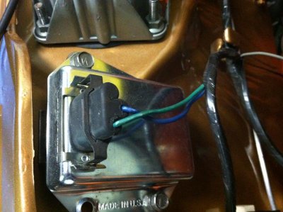
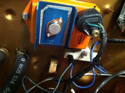
2--Your voltage readings on neg side of coil seem to indicate that the box is not switching. Might not be grounded, might be a bad box, or MIGHT BE a FIVE PIN BOX
You cannot always tell a 4 pin box from a 5, as "some" replacement boxes have 5 pins, but only 4 are hooked up. Since you are using a 2 pin ballast, you may have the opposite problem --you may have inadvertenly gotten an older, 5 pin box
A 5 pin box MUST have a 4 pin resistor. Only way to tell on a box with 5 physical pins is to "ohm out" the 5th pin and decide if it's hooked to anything.
A newer, 4 pin box CAN use either a 2 or 4 pin resistor.
Understand that the Mopar ECU basically replaces points so that means that it SWITCHES the neg side of the coil to ground. Normally, with key on, the coil voltage would be fairly low, IE several volts below the coil + reading
====================================================================
3--In addition to above, check that the box is getting power. You might need to use a straight pin and penetrate the box connector so that you can measure voltage under "real conditions." Assuming this is a 4 pin box, this diagram:
From the above diagram, the far right "existing wire" represents the power coming in from the ignition switch. Notice that it goes to the ballast, and also branches off down to the box. Penetrate that plug terminal with a pin so that you can check voltage AT THAT PIN with the key in "run" and everything hooked up. You should read battery voltage.
4--In that diagram what is NOT shown is the brown, which comes from a separate contact on the ignition switch, through the bulkhead, and to the coil+ side of the ballast THIS WIRE is the ONLY source of ignition voltage in "start" With your meter on the coil+ and "cranking" USING THE KEY and NOT by jumpering the start relay, coil + should read "same as battery" and in no case less than 10V
=======================================================
5--Also, check your reluctor gap at .008" (inches, not metric) with a brass feeler. Last I knew O'Really had 'em
6--You can get some idea of distributor condition by setting your meter to "low AC volts" and hook the leads to the two terminals of the distributor connector. Crank the engine. The distributor should generate about 1V AC
7--In general realize that "new" parts can be defective, whatever the part
8--Your voltages seem low. This would be a good time to check for voltage drop in the igntion harness. I already touched on one check in (4) above. Let's do that in a different manner this time. Clip your meter to coil +, and the other lead to battery + the stud on the starter relay is good. Set the meter to low DC volts. Crank the engine USING THE KEY, and as the engine cranks read the meter. You are hoping to read a very LOW voltage here, as you are reading voltage drop across the harness. If the reading is above .3V, you have a "voltage drop" problem and need to look into this
9--Let's check the "run" circuit the same way. Now hook your meter to an "ignition run" line, (IGN 1) such as the blue alternator field wire, or the "key" side of the ballast --the side which goes to the bulkhead. Hook the other meter lead to battery +. Turn the key to "run" with engine off. Once again, you are hoping for a very low reading, and more than .3V (three tenths of one volt) you have a harness drop problem
The original circuit goes in this path:
Battyer -- starter relay stud -- fuse link -- bulkhead connector -- ammeter circuit -- in harness splice -- ignition switch connector -- through the switch -- back out the switch on dark blue "ignition run" -- back through the bulkhead -- and to the underhood loads.
On 69/ earlier, the above feeds ignition and the regulator IGN terminal
On 70 / later the above adds alternator field (blue), electric choke and idle solenoid if used, and distributor retard if used, and one or two other smog doo dads on some cars.
The most common REASONS for voltage drop in this circuit is -- poor connections in the bulkhead connector, in the ignition switch connector, in the switch, sometimes the ammeter connections or the meter itself, and in very rare but has happened, failure in the factory welded splice. This is a splice in the black ammeter wire under the dash, a few inches into the harness up by the cluster. If further checking should show that might be, you'd have to pull the cluster and untape the harness from the ammeter until you find it.
PLEASE read the always excellent MAD article on ammeters. Even if you do not (now or ever) perform this mod, it points out the hows and whys of what happens with these old girls.
http://www.madelectrical.com/electricaltech/amp-gauges.shtml
The simplified diagram down the above page shows the main power dist. in these cars. What they left off was through the ign switch and back out the bulkhead
By the way, my all time favorite car was my old 440-6 70 RR. If I could afford it I'd have more than one
http://moparforums.com/forums/f62/my-old-ride-back-day-596/
I have no good photos anymore
The car before I owned it, George, my friend and original owner, had just trophied in pure stock, probably at Lions
Ya. Me. When I was a young little SOB


