• When you click on links to various merchants on this site and make a purchase, this can result in this site earning a commission. Affiliate programs and affiliations include, but are not limited to, the eBay Partner Network.

One step forward two steps back

Jbland

Active Member
Local time
4:28 PM
Joined
Oct 24, 2012
Messages
32
Reaction score
0
Location
Texas
Ok here goes I started w a few issues on my 68 charger 318 and now I have many. Problem one, car will start but stops running immediately unless I hold the key in the crank position. Problem two, battery is getting overcharged upwards of 16 volts, almost blew it up the other day. I have new alt, batt, voltage reg, ammeter. At my wits end with electrical any info will help! Thank you!
 
I'm not sure to be honest. I just bought an OEM regulator at oreillys how can I decifer if its mechanical?

- - - Updated - - -

Checked all grounds, cleaned all terminals and went to bare metal on engine/body connections. I'm getting no voltage at all from ballast resistor but I'm not sure it's even hooked up right. Also it looks to have an electronic ignition module next to the battery does that eliminate the need for the ballast?
 
Post some Photo's of your system, it will be helpful to diagnose problem.....
 
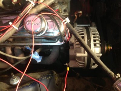
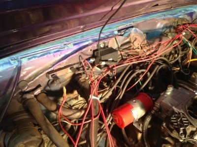
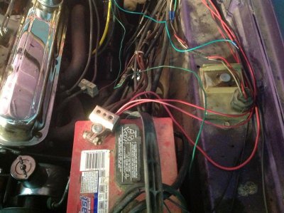
Here are some pics of my charging system.
 

Attachments

  • image.jpg
    image.jpg
    65 KB · Views: 224
  • image.jpg
    image.jpg
    84.6 KB · Views: 214
  • image.jpg
    image.jpg
    76.8 KB · Views: 217
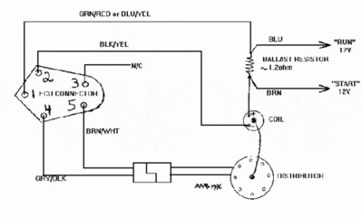
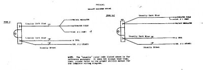
Lots of red wire there. Trace slowly. Chrysler ignition switches have two outputs through the firewall bulkhead. Blue has power with key on, no power in the crank position. Brown wire has power in the crank position only. You must tie the 2 together. This tied pair will feed 3 locations. #1 the light blue wire at the ignition box, #2 the ballast resistor, #3 voltage regulator. Make sure all 3 of these locations have power with key on and during crank. The 2nd wire from the ballast resistor feeds the + side of the coil. I'm assuming this is a single terminal alternator (not including the bolt on output wire). 2nd wire from the regulator feeds the alternator field. The regulator must be grounded. The ignition box must be grounded. The other three wire from the ignition box feed the negative side of the coli and the distributor. You ave these correct or it wouldn't have run at all.
Test these connections and let me know what you find.
Doug
 
Re:

Lots of red wire there. Trace slowly. Chrysler ignition switches have two outputs through the firewall bulkhead. Blue has power with key on, no power in the crank position. Brown wire has power in the crank position only. You must tie the 2 together. This tied pair will feed 3 locations. #1 the light blue wire at the ignition box, #2 the ballast resistor, #3 voltage regulator. Make sure all 3 of these locations have power with key on and during crank. The 2nd wire from the ballast resistor feeds the + side of the coil. I'm assuming this is a single terminal alternator (not including the bolt on output wire). 2nd wire from the regulator feeds the alternator field. The regulator must be grounded. The ignition box must be grounded. The other three wire from the ignition box feed the negative side of the coli and the distributor. You ave these correct or it wouldn't have run at all.
Test these connections and let me know what you find.
Doug


Ok so I found the blue ign and brown crank wires at the bulkhead. Are you saying I need to splice the two together? One end of the ballast goes to coil but where does the other end connect to?Regulator is connected to ignition and grounded well as is control box.
 
Yes splice them. Then reread above and make sure you have power at the 3 locations i mentioned in key on and in crank. Then let me know.
Doug
 
I would not cut anymore wires until you get more familiar electronic ignition system....Your engine bay electrical system needs to be cleaned up.I would re traced the wires, ohmed out the wires not being used & mark them for removal....

Read this link, its very helpful.......
http://www.allpar.com/fix/electronic-ignition.html
Troubleshooting.......
Electronic ignitions work in exactly the same way as a point system - only much better. Where as the points are a mechanical switch the transistor in an electronic ignition is an electrical switch.

There are three factors which determine how well a points switch works;

1) How much current it can interrupt (bigger is better)

2) How fast it can interrupt this current (smaller is better)

3)How long it allows current to build up (dwell angle, bigger is better)

Even the most basic type of electronic ignition is a great improvement over normal points because of the faster switching speeds, big power handling capability and huge dwell angles.

The electronic ignition is made up of three parts;

1) THE RELUCTOR
This is a rotating magnet with "teeth" on it (like a gear wheel) corresponding to the number of cylinders the engine has. As it rotates, its teeth pass very close to the pick-up coil and causes the magnetic field in that coil to go up and down.
The reluctor has the same function as a distributor cam and often sits in its place.

2) THE PICK-UP COIL
This is a small wire coil which sits close to the reluctor. As the reluctor rotates, a voltage spike is induced into this coil by the reluctors magnetic field which tells the transistor in the amplifier when to interrupt the primary current in the ignition coil.
The pick-up coil takes the place of the rubbing block in a points system.

3)THE AMPLIFIER
This is actually the wrong name for what it does. The current to the coil is not amplified in this type of system. All that happens is that when it senses a voltage spike from the pick-up coil, the amplifier switches off the current to the ignition coil primary winding creating a spark from the coil.
The amplifier is the equivalent of the contact points.

Some systems use an optical device to trigger the amplifier. Instead of a pick-up coil they have a photo-cell which puts out a voltage when light falls on it. The reluctor in this case is a special rotor which has slots in it. When the slots line up between the photo-cell and a light source, a spark is generated.

TROUBLESHOOTING THE CHRYSLER ELECTRONIC IGNITION
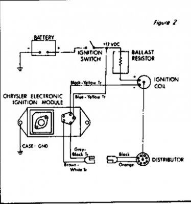
1/Remove the wiring connector from the orange box amplifier. This is a view of the rubber connector when removed and looking at the bottom.


2/Turn the ignition switch ON.
You should have battery voltage (within 1 volt) between earth and pin 1 (blue/yellow wire). Also pin 2 (black/yellow).

3/Turn the ignition OFF.
Pins 4 & 5 connect to the pick-up coil in the distributor. Connect an Ohm meter accross these two pins. The resistance should be within 150-900 ohms (400-600 prefered). If is isn't detatch the dual connector at the distributor and check there. If the coil is still not within spec replace it. Connect one lead of your ohm meter to earth and the other to either coil pick-up connector. If you get any reading at all replace the pick-up coil.

Pin 3 in my diagram is not used but should be connected to earth. Check this.

SET THE RELUCTOR GAP
The reluctor gap should be set with a non-magnetic feeler guage. 10thou in early ignitions and 8thou in those made after 1977. Set the gap by holding a feeler guage that is 2thou smaller against a reluctor tooth and move the pick-up against it. Tighten the adjusting screw and you will find that the gap is now right when you try it.
 

Attachments

  • picture.JPG
    picture.JPG
    108 KB · Views: 182
  • elect_ign_wir3.gif
    elect_ign_wir3.gif
    15 KB · Views: 206
  • 416.jpg
    416.jpg
    22.1 KB · Views: 185
Yes splice them. Then reread above and make sure you have power at the 3 locations i mentioned in key on and in crank. Then let me know.
Doug

Ok so I spliced the wires and engine is running again. After a trip around the block though the voltage at the battery is already at 15.7volts so I still have an overcharging issue. Would the ballast help this?
 
The ballast is to cut the voltage for the spark. Sounds like you have a bad regulator that is allowing over charge or maybe there is not a good connection between the regulator and the alternator. Or maybe the wires are not connected correctly between the regulator and the alternator, like maybe the wrong wire going to the field post on the alternator.
 
Auto Transport Service
Back
Top