• When you click on links to various merchants on this site and make a purchase, this can result in this site earning a commission. Affiliate programs and affiliations include, but are not limited to, the eBay Partner Network.

Re-Rebuilding the 440-493 in a 1970 Charger

Those seal the reservoir to the pump. These stud/bolts thread through them.


714 R.JPG
 
If you try it again I would test it out of the car. All you need is a 1/3hp electric motor and a jig made out of wood to hold the motor and pump to try it. I try all pumps and steering boxes before they go in the car. On the power steering relief valve it should fall in and out of the pump body, 800 grit with oil works well, do the valve and pump body. You do not want to go overboard on it as a mirror finish is not good either. I am not a fan of those factory power steering coolers, a loop of 3/8 steel line in front of the radiator would be better. All I can tell you is my truck at over 8000# with that hydroboost, Delphi steering box the same pump, and a 1-1/4" bore master is velvet touch for brake feel. Easy pedal, low travel and solid as a rock. I am sure you checked but that screen in the end of the relief valve needs to be clean. Pics of my ghetto rig but it works.

20221121_122125.jpg


20221121_122103.jpg
 
Last edited:
KD, I would re-install the power booster and vacuum pump setup you had before that worked well. I've never run one of those vacuum pumps, but in my research it appears there are several new quieter pump options also now available. Plus, my preference would be to get a saginaw mopar pump back on there instead of the chevy hodge-podge stuff (although it may work well).

The hydroboost setup SEEMS like a good option, BUT - if it were on my classic mopar, for some reason I don't like the idea of it being tied into the power steering system. Might work fine for the brakes, but how do I know for sure it won't compromise the steering at some point in the future? It may not, but...it might!
 
One of the benefits of multiple choices is that you have options.
One of the drawbacks of multiple choices is that you have to pick ONE of those options.
Yeah, my thoughts on using the hydroboost are closely tied to an appreciation for the gesture on the part of Cass Eslick/Dr Diff. If I had to pay out of pocket, I wouldn't have gone that way.
In theory, it does seem a bit weird to trust all the brake boost to a drive belt and pump but it has been done many times with very low failures to my knowledge.
A vacuum pump can fail too. I don't know how closely the failure rate is between a vacuum pump versus a power steering pump and belt.
I'm going to gather the parts today and test the vacuum pump to see if it still works. I have teetered back and forth on which way to go but have been leaning toward the vacuum system almost entirely until DWAYNE teased me about revisiting the hydroboost option!
 
Here we go again. Admitting defeat sucks but it is the way that some lessons are learned best.
I tested this pump:

EB5A0383-8455-47B6-9AB9-869C6D76BA35.jpeg

B1D47851-EB55-45F5-A8B9-489C2EE4EF6A.jpeg


It made 22” of vacuum.
Of course I had to clean it. In doing so most of the gold anodizing came off. I went ahead and clear coated it.

4EB8DD54-12AB-4944-97E3-51233FE6D706.jpeg
5E2F4B34-546A-41B9-A75C-01F08B4B4FBD.jpeg


The bracket was cleaned and painted satin black. It is almost silly to refinish this pump since it will sit in “harms way” inside the left front wheel well behind the headlights. I mounted this very pump there before. I might make some shield to protect it from road debris, small rocks and such.
When running, it isn’t very loud. It surely gets drowned out by the sounds of the engine.

In the past, I’ve used this iron master cylinder, sized 15/16”.

image.jpg


It worked but was heavy. It also isn’t really right for a 4 wheel disc arrangement.
I have this one leftover from the hydroboost effort:
1944803D-39D1-47EB-A249-4D00C30CA508.jpeg

It is 1 1/8”. Aluminum with a big reservoir. This should provide adequate pressure for a vacuum boosted setup.
From what I’ve read, going to a larger bore master cylinder will result in shorter pedal travel before brake engagement but a firmer pedal.
I will find out.

75FE374C-1846-4DFA-BF1C-CA097225358C.jpeg
 
Last edited:
Here we go again. Admitting defeat sucks but it is the way that some lessons are learned best.
I tested this pump:

View attachment 1376743
View attachment 1376744

It made 22” of vacuum.
Of course I had to clean it. In doing so most of the gold anodizing came off. I went ahead and clear coated it.

View attachment 1376746View attachment 1376747


The bracket was cleaned and painted satin black. It is almost silly to refinish this pump since it will sit in “harms way” inside the left front wheel well behind the headlights. I mounted this very pump there before. I might make some shield to protect it from road debris, small rocks and such.
When running, it isn’t very loud. It surely gets drowned out by the sounds of the engine.

In the past, I’ve used this iron master cylinder, sized 15/16”.

View attachment 1376749

It worked but was heavy. It also isn’t really right for a 4 wheel disc arrangement.
I have this one leftover from the hydroboost effort:View attachment 1376748
It is 1 1/8”. Aluminum with a big reservoir. This should provide adequate pressure for a vacuum boosted setup.
From what I’ve read, going to a larger bore master cylinder will result in shorter pedal travel before brake engagement but a firmer pedal.
I will find out.

View attachment 1376734
I’m no brake expert, but I think you may need to look at the volume of fluid needed by your calipers. The master cylinder piston needs to have the capacity to displace enough fluid.
Then work out the leverage needed by the pedal.
 
This master cylinder was what Dr Diff listed to use with the hydroboost. My guess is that the MC doesn’t care whether I use a HB or the vacuum booster.
I looked in my metal scrap bin and found the bracket I used to mount the pump.
941FD78D-AF89-42AD-9895-0CAB665990C8.jpeg

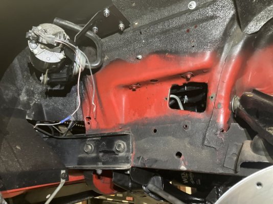
The front most two bolts that attach the fender to the apron have exposed threads in the wheel well.


image.jpg


This is just a simple piece of 14 gauge sheet metal.

F4C209FB-264A-4C24-91F3-3A9335571507.jpeg

Once it is secure, the bottom will be parallel to the ground.

The bracket has rubber isolaters to minimize vibrations.

75F70C9E-C696-4A00-B33A-A677C29BDC4A.jpeg


The mounting bracket is dry enough to attach.

7BA623AE-DACA-493C-B118-A5C6D10D71B2.jpeg


Simple 3 bolt arrangement.

523F74EB-4575-4EAA-B41A-587D12680838.jpeg


This is the intake hose. Should there be some type of filter on the end?

image.jpg
 
I’m no brake expert, but I think you may need to look at the volume of fluid needed by your calipers.
The last arrangement I had was with large 2.75” front calipers and a 15/16” master cylinder. This one is with twin 1.59” pistons in the front calipers and this 1 1/8” MC. The new calipers have less surface area but will have more fluid volume to move them.

The bracket dried enough to bolt it all up.

B01CA366-F622-4BCD-8360-1F1A9DB46943.jpeg


This is far enough ahead that it doesn’t come close to the tire. It has a 11/32” serrated nipple. 3/8” hose will slide on with some effort. The last time, I ran the hose through the forward alignment cam window.

image.jpg

That worked fine. I’d love to run the line through the rear alignment window but the tire rubs the rail and would likely destroy the hose.

image.jpg


Ha ha… green paint showing through just like a blonde with dark hair on the scalp!
 
I took a stock cover and folded the edge over to both close off the "window" and to provide a ledge to rest the vacuum hose on.

872 R.JPG


Inside, it snakes up the apron...

873 R.JPG


It will sit alongside the existing wiring and sort of blend right in.

874 R.JPG


Next will be the wiring for the pump. I still have the switch in the console so it will be a fairly simple matter of running the wires and securing them.

The Booster uses this aluminum spacer/adapter:

877 R.JPG


I haven't measured it but it may be close to the thickness of this bracket:

878 R.JPG


Regardless, if the master cylinder and adapter fit, there is some amount of adjustment in this rod that engages the master cylinder piston.

875 R.JPG


The end has a pair of flat spots to hold it still and it is threaded inside for the "nub".


876 R.JPG


I had it set about 5/16" out with the other master cylinder. There are enough threads to stick it out further if needed.
 
You’re attention to detail is remarkable. Conveniently routing things, without being too over the top of hiding everything. It looks great!
 
Thank you. I want things to either hide or look as if they belong. That 3/8" vacuum line will look better than the 3 lines for the hydroboost.
22" of vacuum from this pump was more than enough when I used it before. The pump and bracket added 4 lbs but are worth the weight.
 
The vacuum pump is wired in. I ran an inline fuse and the power source is protected through a relay.
I put an auxiliary fuse panel and Bosch relay in 3 years ago on the advice of 1 Wild R/T (Randy) .
The extra fuse block allows me to power the extra electrical stuff without making a rats nest of the original fuse panel. The stock panel isn’t exactly easy to get to anyway.
I’ve been thinking about plumbing the system without using the distribution block. This is how it is plumbed now.

00F2D5C0-25B1-4923-A2C2-080EEA1346F8.jpeg

At the 12:00 position is the line from the master cylinder to the front lines. Just below that at 9:00 and 3:00 is the left and right front brake lines. The wire plug serves the brake warning light.
I am thinking of using a “T” there.
The rear line normally comes in from the front side.

6A3CF2A2-B60A-4399-AF54-547D8CDFC330.jpeg

I could simply connect the line like so:

9FA3EDA8-F3A8-4DC0-84C5-BD61CA69DAFC.jpeg
F792AD9B-3B5F-46D9-9189-B67754882C2A.jpeg


This seems so simple. Others may have done this but I’ve never seen it. I figure that as long as nothing leaks, it should be fine. Being without a warning light isn’t a problem. A low pedal would be warning enough.
 
The brake booster is in along with the master cylinder. I'm getting good at this.....I've been under the dash numerous times over the past month and a half. I can almost understand things upside down as easy as right side up.
The bolt pattern to secure the hydroboost, the manual master cylinder and the brackets for the 73-76 A body vacuum booster are the typical 4 bolt rectangle style. The nuts to secure each of these setups are accessible using 3/8" extensions, wobbly sockets and good lighting to see.
With the booster bolted up, I measured the thicknesses of these:

877 R.JPG
878 R.JPG

They were within a few thousands of each other so I figured that the aluminum master cylinder would just bolt right on.

885 R.JPG


Not exactly.

887 R.JPG


Before the body of the master cylinder was flat against the adapter, I could feel the pushrod trying to press the MC piston. The master cylinder needed a spacer. I had some 1/4" aluminum stock.....

888 R.JPG


Cut, holes drilled, a file to dress the edges...

889 R.JPG


Now the 1 1/8" master cylinder is in place.

890 R.JPG
891 R.JPG


There is barely enough threads on the studs to cinch down the master cylinder.
Next will be to make the 3rd set of brake lines since this project started. I really hope that this arrangement works out.
A thread on FABO included a member that stated that power brake systems need to be bled with the engine OFF. I thought it was a typo on his part. He included a video from a guy that rebuilds brake boosters. The man claims that by bleeding with engine vacuum, it may push too hard on the booster when there is air in the brake lines....leading to booster failure.
I'm not a trained mechanic but I have been working on cars for 40 years. I have never bled brakes with the engine off except in manual brake cars. I've never broken any brake boosters either.
Strange, huh?
 
Here is a curious thing....
As I was bench bleeding the master cylinder, I could see the front port getting fluid before the rear. Bubbles started in the front, followed by the rear.
Through the travel of the master cylinder piston, it was clear that the first 1/3 of the travel, the rear port didn't seem to get any pressure.
 
I started another thread and a helpful member responded with a tech sheet.....

1669179733775.png


I don't know why a sheet like this wasn't included in the box that mine came in. Mine is a Raybestos unit.
I knew that something was wrong but it wasn't clear to me.
With the brake lines connected the traditional way, the REAR is getting pressure before the front.
This can't be right.
I bench bled a stock iron 15/16' MC. The front and rear get pressure at the same time.
I bench bled the Dr Diff aluminum 15/16" MC and it was exactly like the larger 1 1/8" version: Pressure and bubbles at the front port before the rear.
There was no tech sheet in the box with these master cylinders.
 
Last edited:
Cass/Dr Diff responded and confirmed that these MCs have ports that have the traditional pattern.
This is the 1 1/8" aluminum MC that I have in the car now.

RAYBESTOS MC39178 Specifications
Number of Ports2
Primary Port Thread A1/2"-20
Secondary Port Thread A9/16"-20

That shows the different port sizes and it shows that the smaller thread is for the front. That reflects what I found. I was wrong....the pattern is the traditional. I'm still confused as to why the rear brakes would get pressure first.
 
Auto Transport Service
Back
Top