• When you click on links to various merchants on this site and make a purchase, this can result in this site earning a commission. Affiliate programs and affiliations include, but are not limited to, the eBay Partner Network.

440 with Engine Plate

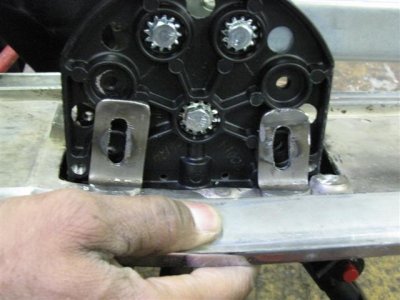
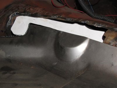
Sorry for the delay in answering your ? I have 650-675ish hp.The car is mostly a drag car with VERY limited street use. I can use pump gas but just not very street friendly. I am not using a mid plate. I didn't know any better when I put my tabs in. I wished I would have put them on the backside because I have had to remove the motor once and it was a pain. The other way would have been alot easier. I may redo it in a couple years when I remove the motor to freshen it up. I never do it right the first time so I end up doing it over in the long run. Oh well that is how others learn.
 
67 B-Body My students echo your sentiments. They think I should paint my whole car that color. Blue is my favorite color, but I think the orange is shocking and different. Cars nowadays don't use color schemes like that anymore. It is different and bold! I won't have to make that choice for a while at my present rate. Thanks and no thanks; I have plans for that pump keeping this beast cool while I am hot!
 
Here are some pics of the tranny and torque converter going in with the flex plate. The one shot of me getting ready to prime the engine through the oil pump.
 

Attachments

  • IMG_0912 (Small).jpg
    IMG_0912 (Small).jpg
    50.6 KB · Views: 235
  • IMG_0913 (Small).jpg
    IMG_0913 (Small).jpg
    57.7 KB · Views: 230
  • IMG_0914 (Small).jpg
    IMG_0914 (Small).jpg
    49.2 KB · Views: 258
  • IMG_0920 (Small).jpg
    IMG_0920 (Small).jpg
    65.6 KB · Views: 245
Now I need your help again. I know some of you have put aftermarket radiators in. I am trying to do the same thing, but I have no place to to bolt it in. There is a 1/8" flange that is not big enough to put a bolt through. I am thinking about using some channel stock to hold it in place. I do not have the means to weld aluminum. If you can give me some input I would love to hear from you. As you know a picture is worth a thousand words. Thanks in advance for your help! I am posting some pics of the radiator in question.
 

Attachments

  • IMG_0921 (Small).jpg
    IMG_0921 (Small).jpg
    61.1 KB · Views: 256
  • IMG_0922 (Small).jpg
    IMG_0922 (Small).jpg
    51.1 KB · Views: 255
I was waiting for some parts to arrive and they are here. The transmission dip stick and header gaskets. I ordered TTI gaskets from Mancini and they were taking forever getting here, so I switched up. Also pictured is my Chetah shifter I bought a few years back, which I hope to install soon.
 

Attachments

  • IMG_0988 (Small).jpg
    IMG_0988 (Small).jpg
    53.9 KB · Views: 213
  • IMG_0987 (Small).jpg
    IMG_0987 (Small).jpg
    42.1 KB · Views: 258
  • IMG_0986 (Small).jpg
    IMG_0986 (Small).jpg
    57.8 KB · Views: 248
  • IMG_0984 (Small).jpg
    IMG_0984 (Small).jpg
    50.2 KB · Views: 291
  • IMG_0983 (Small).jpg
    IMG_0983 (Small).jpg
    51.9 KB · Views: 220
This is my solution to the radiator fabrication issue. I want to thank John for giving me this idea. I bought a 3' piece of 1/8" angle iron from Lowes and cut it in half, then welded it together to make a U-channel. It had a zinc coating on it so I took that off with the wire wheel and grinder. Then I used these 3" bolts with hooks on one end to secure the U-channel to come brackets I fabbed from some square stock I had laying around. I love working with that plasma cutter. It makes life so much easier. I took some old fuel hose and placed the bolts through it so the radiator can rest on it and take up some of the vibration. I used those same bolt hooks to secure the top of the radiator. I am using some plastic donuts I fabbed from plastic tubes and I am sandwiching them between rubber washers to finish this off.
 

Attachments

  • IMG_0985 (Small).jpg
    IMG_0985 (Small).jpg
    53.2 KB · Views: 218
  • IMG_0989 (Small).jpg
    IMG_0989 (Small).jpg
    54.9 KB · Views: 234
  • IMG_0990 (Small).jpg
    IMG_0990 (Small).jpg
    63.2 KB · Views: 222
  • IMG_0991 (Small).jpg
    IMG_0991 (Small).jpg
    44.7 KB · Views: 227
  • IMG_0992 (Small).jpg
    IMG_0992 (Small).jpg
    40.8 KB · Views: 251
A few more...
 

Attachments

  • IMG_0997 (Small).jpg
    IMG_0997 (Small).jpg
    56.7 KB · Views: 227
  • IMG_0996 (Small).jpg
    IMG_0996 (Small).jpg
    40.9 KB · Views: 228
  • IMG_0995 (Small).jpg
    IMG_0995 (Small).jpg
    45.2 KB · Views: 216
  • IMG_0994 (Small).jpg
    IMG_0994 (Small).jpg
    59.3 KB · Views: 238
  • IMG_0993 (Small).jpg
    IMG_0993 (Small).jpg
    53.6 KB · Views: 231
Has anyone used the aluminum driveshaft in a dragcar? How do they hold up?
 
Help!!!

I need your help again ladies and gentlemen. As you can see from the pics above I have the Cheatah Turbo action shifter with reverse valve body and the console that goes with it. I tried to put this unit together today and found that the console has a manufactured split in the end. My question is do I have to cut the console around the rails that protrude out of the end or do I have the wrong console? I don't mind cutting it, I just don't want to ruin it if there is a mistake and it must be sent back. If anyone is running the Cheatah shifter and you have a pic of how you did it, I would appreciate you sharing that. Again I thank you in advance for your help!!!
 
OK I took the plunge after considering my options with the limited knowledge I have. I am going to try and marry the old school console with the new Cheetah shifter. I removed the panel and cut a hole the size of the shifter base. Now I have to find a way to secure it. I am going to fabricate some brackets that will help to hold this baby together. I tried using some sheet metal but it was too thin, so I went out and picked up some 1/8" steel 1" wide. I will layout the lines for the bends I need to make and the holes I need to drill. Here are a few pics I have taken of what I have gotted done so far. I do want you to know that I have considered the cost of cutting an original shifter, but that is why I bought it in the first place!
 

Attachments

  • IMG_1000 (Small).jpg
    IMG_1000 (Small).jpg
    55.6 KB · Views: 199
  • IMG_1001 (Small).jpg
    IMG_1001 (Small).jpg
    64.6 KB · Views: 199
  • IMG_1002 (Small).jpg
    IMG_1002 (Small).jpg
    55 KB · Views: 228
  • IMG_1003 (Small).jpg
    IMG_1003 (Small).jpg
    60.4 KB · Views: 213
  • IMG_1005 (Small).jpg
    IMG_1005 (Small).jpg
    45.6 KB · Views: 203
The small green brackets are the sheet metal ones that I am throwing away. The large rubber pipe connecter I am using as a filler material for the gap between the edge of the shifter base and the console panel. The shifter will not sit flat on the console plate because it is curved. I could cut the base of the shifter to fit the curve of the console plate, but I thought the rubber would be equally effective and a whole lot easier. Why the round rubber pipe sleeve? I could not find a flat piece of rubber anywhere, so I will cut this to fit and see how it works. The scratch awl is pointing to the gap between the shifter and the console plate. I started cutting the holes in the steel flat stock. Enjoy!
 

Attachments

  • IMG_1009 (Small).jpg
    IMG_1009 (Small).jpg
    43.8 KB · Views: 212
  • IMG_1008 (Small).jpg
    IMG_1008 (Small).jpg
    57.9 KB · Views: 196
  • IMG_1007 (Small).jpg
    IMG_1007 (Small).jpg
    52.1 KB · Views: 213
  • IMG_1006 (Small).jpg
    IMG_1006 (Small).jpg
    54.1 KB · Views: 215
I gave the camera to my students today and they went crazy taking pics of the console mod I have going on and the floor replacement on the driverside. I will start with the brackets and console stuff.
 

Attachments

  • IMG_1011 (Small).jpg
    IMG_1011 (Small).jpg
    50.2 KB · Views: 181
  • IMG_1012 (Small).jpg
    IMG_1012 (Small).jpg
    51.2 KB · Views: 252
  • IMG_1014 (Small).jpg
    IMG_1014 (Small).jpg
    49.6 KB · Views: 232
  • IMG_1015 (Small).jpg
    IMG_1015 (Small).jpg
    54.8 KB · Views: 182
  • IMG_1016 (Small).jpg
    IMG_1016 (Small).jpg
    53.2 KB · Views: 188
The pics are mixed up. Forgive me but this is the order they were taken in.
 

Attachments

  • IMG_1023 (Small).jpg
    IMG_1023 (Small).jpg
    46.1 KB · Views: 219
  • IMG_1022 (Small).jpg
    IMG_1022 (Small).jpg
    51.5 KB · Views: 186
  • IMG_1020 (Small).jpg
    IMG_1020 (Small).jpg
    43 KB · Views: 230
  • IMG_1018 (Small).jpg
    IMG_1018 (Small).jpg
    51.5 KB · Views: 227
  • IMG_1017 (Small).jpg
    IMG_1017 (Small).jpg
    48.5 KB · Views: 186
I have some pics of the new floor being chiseled out. First I had my students make a pattern by taping paper to the bottom of the new floor pan. Then we put the floor pan in place and they traced the outline of the floor cut out from the bottom of the car with a sharpie. I then cut away the excess paper from the pattern with a two inch overhang. Then I cut with the plasma cutter. I put it in place and saw where I could trim a little more away until I had an exact fit. Then with the floor panel in place there was an area where the manuel shifter hump removal left an odd shaped hole. I had my students put a piece of paper over the hole from under the car, while another student traced the shape from inside the car. I will cut that shape out tomorrow and see how it fits. I will also add two inches for the lap weld.
 

Attachments

  • IMG_1025 (Small).jpg
    IMG_1025 (Small).jpg
    38.5 KB · Views: 229
  • IMG_1026 (Small).jpg
    IMG_1026 (Small).jpg
    32.9 KB · Views: 184
  • IMG_1027 (Small).jpg
    IMG_1027 (Small).jpg
    34.8 KB · Views: 202
  • IMG_1028 (Small).jpg
    IMG_1028 (Small).jpg
    39.4 KB · Views: 178
  • IMG_1029 (Small).jpg
    IMG_1029 (Small).jpg
    49.4 KB · Views: 176
More of the same!
 

Attachments

  • IMG_1035 (Small).jpg
    IMG_1035 (Small).jpg
    57.1 KB · Views: 178
  • IMG_1034 (Small).jpg
    IMG_1034 (Small).jpg
    69.9 KB · Views: 201
  • IMG_1033 (Small).jpg
    IMG_1033 (Small).jpg
    63.8 KB · Views: 187
  • IMG_1032 (Small).jpg
    IMG_1032 (Small).jpg
    54.8 KB · Views: 206
  • IMG_1031 (Small).jpg
    IMG_1031 (Small).jpg
    56.4 KB · Views: 227
More!
 

Attachments

  • IMG_1036 (Small).jpg
    IMG_1036 (Small).jpg
    52.3 KB · Views: 203
  • IMG_1037 (Small).jpg
    IMG_1037 (Small).jpg
    56.2 KB · Views: 177
  • IMG_1038 (Small).jpg
    IMG_1038 (Small).jpg
    61.2 KB · Views: 190
I was painting the brackets and letting them dry while I cut off a piece of rubber to fill in the gap between the shifter base and the console panel.
 

Attachments

  • IMG_1045 (Small).jpg
    IMG_1045 (Small).jpg
    61.3 KB · Views: 186
  • IMG_1042 (Small).jpg
    IMG_1042 (Small).jpg
    27 KB · Views: 208
  • IMG_1041 (Small).jpg
    IMG_1041 (Small).jpg
    39 KB · Views: 191
  • IMG_1040 (Small).jpg
    IMG_1040 (Small).jpg
    38.1 KB · Views: 165
  • IMG_1039 (Small).jpg
    IMG_1039 (Small).jpg
    38.7 KB · Views: 182
A few more!
 

Attachments

  • IMG_1046 (Small).jpg
    IMG_1046 (Small).jpg
    50.7 KB · Views: 194
  • IMG_1050 (Small).jpg
    IMG_1050 (Small).jpg
    58.3 KB · Views: 190
  • IMG_1053 (Small).jpg
    IMG_1053 (Small).jpg
    35.3 KB · Views: 175
  • IMG_1054 (Small).jpg
    IMG_1054 (Small).jpg
    34.9 KB · Views: 174
  • IMG_1055 (Small).jpg
    IMG_1055 (Small).jpg
    41.4 KB · Views: 187
As you may have noticed there is an odd shaped hole on the transmission tunnel not covered by the floor. I had my students make this template and I just added an inch all around and cut it out.
 

Attachments

  • IMG_1057 (Small).jpg
    IMG_1057 (Small).jpg
    36.3 KB · Views: 199
  • IMG_1056 (Small).jpg
    IMG_1056 (Small).jpg
    35.3 KB · Views: 165
I finally have the shifter married to the console.
 

Attachments

  • IMG_1058 (Small).jpg
    IMG_1058 (Small).jpg
    56 KB · Views: 202
  • IMG_1059 (Small).jpg
    IMG_1059 (Small).jpg
    53.8 KB · Views: 178
  • IMG_1060 (Small).jpg
    IMG_1060 (Small).jpg
    58.8 KB · Views: 177
  • IMG_1061 (Small).jpg
    IMG_1061 (Small).jpg
    61.1 KB · Views: 219
  • IMG_1062 (Small).jpg
    IMG_1062 (Small).jpg
    64.6 KB · Views: 174
Auto Transport Service
Back
Top