Water pump flow does appear to facilitate radiator cooling up to a point. The primary flow restriction appears to be the thermostat and radiator. This article indicates that this may cause a sight positive pressure at the upper hose.
Since the water pump flow increases with engine RPM, but this does not facilitate greater flow in the radiator due to thermostat or radiator restriction, the time in radiator for cooling may be a moot point. Whether the positive pressure may cause cavitation is another issue. In a full and closed system with no air, it seems like the flow will be determined by the thermostat or radiator flow capacity. Someone above my pay grade will have to answer this.
It is a 50 year old Plymouth, not a nuclear submarine, and although they are overhead in my area constantly, I have never been picked up by a P3 to my knowledge.
The boys on the boomers tell me they have to create noise for the P3's to find them in training simulations.
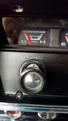
The time in radiator question will hopefully be answered when I run the car tomorrow with no thermostat and see if it runs a cooler high temperature.
I have people saying if you want it to run 165, run a 165 thermostat and if you want it to run 180 run a 180. Life would be good should things be that simple. Running 215 on a 195 has proven that to me so far.
Update tomorrow.
Water Pumps
Usually centrifugal pump is used for the circulation of water in the cooling system. Figure 12.7 shows the construction of a centrifugal pump, which is driven by a fan belt mounted on a common shaft with the fan. The centrifugal pump is non-positive in action and does not build up high pressure. It simply consists of a casing inside which an impeller containing vanc-s is rotated. Water enters the inlet pipe from the bottom of the radiator and is directed by a passage to the centre of the impeller where it is caught by the rotating vanes. Due to centrifugal force the water is thrown out into the stationary casing. The kinetic energy imparted to water by the impeller is converted into pressure energy in the stationary casing so that a pressure difference is created between the inlet and outlet of the pump causing forced circulation of water in the system. Since the impeller is always submerged in the water, a seal is used to make a water tight joint where the impeller shaft passes through the casing.

Fig. 12.7. Sectional view of a centrifugal pump.
The water pump on a V-8 engine at cruising speed pumps about 475 litres per minute of operation. Depending on the restriction of the thermostat and radiator, the water pump may create a slight positive pressure at the upper hose. The pump insures an adequate flow of coolant through the water jackets and radiator. The pump usually causes a flow of about 0.3 to 0.6 m/s through the radiator tubes. A slightly higher velocity although produces a greater efficiency in the radiator but causes a higher power loss at the water pump. Coolant flow with a velocity more than 1.8 m/s is considered a waste of power.
The water pump impeller shaft is supported by a double set of ball bearings which are permanently lubricated and sealed. A carbon seal is used to keep the coolant from leaking along the pump shaft. A weep hole in the housing allows any coolant that seeps past the seal to escape from the pump preventing corrosion or damage to the pump bearings.
12.4.2.


