• When you click on links to various merchants on this site and make a purchase, this can result in this site earning a commission. Affiliate programs and affiliations include, but are not limited to, the eBay Partner Network.

MAD/Nacho Electrical Wiring mods

Yes, 4 gauge wiring recommended with 80 amp fuse.

Maybe it would be better to run a second battery with a separate charge wire from the alternator?

woah!!!!... LOL... That's a diff stuff... just like hook up a second starter motor!!!
 
This could make a diff story about the ammeter setup. And I guess you will be using a capacitor
 
This could make a diff story about the ammeter setup. And I guess you will be using a capacitor

Well im not sure. If I run a second battery, with a battery isolator would i still need a capacitor?

Also, if I ran a second battery then it shouldn't affect the ammeter. Correct?
 
well, if all the power comes from the same alt, both should be recharged, so both should be hooked up somehow to the ammeter. And with engine off, if you put max volume, pretty sure you ammeter could read max discharge or close.

( Damn! I'm still thinking on what you have in mind to need an amplifier requiring a 4 gauge wire and 80 fuse LOL ).

I'm a sound tech, and the amplifiers used use to suck, 15-20 amps... sure at 110-120 Volts which makes of course difference
 
Last edited:
well, if all the power comes from the same alt, both should be recharged, so both should be hooked up somehow to the ammeter. And with engine off, if you put max volume, pretty sure you ammeter could read max discharge or close.

( Damn! I'm still thinking on what you have in mind to need an amplifier requiring a 4 gauge wire and 80 fuse LOL ).

I'm a sound tech, and the amplifiers used use to suck, 15-20 amps... sure at 110-120 Volts which makes of course difference


Now I have never used ( yet ) a battery isolator,
But it looks like they will charge the secondary battery, and keep the primary battery from discharging.
So if the primary battery doesn't get discharged, even with the engine off and at max volume then the ammeter shouldn't show a discharge.
 
If you source from the alt side, any power coming from batt will be read by the ammeter with engine off
 
what wire harness do I you use for my 1970 roadrunner
 
So if the primary battery doesn't get discharged, even with the engine off and at max volume then the ammeter shouldn't show a discharge.

The function of a battery Isolator is to charge two separate battery systems from one alternator. Would want the isolator to be current rated to at least the rating of the max alternator output. Marine stores were a good source for quality isolators when I was doing this work professionally, quite a while ago.

No discharge current would flow to the other system but both batteries would receive charge current. No current flow in the second system would register on the ammeter.

All audio components power would need to be sourced from the second system only, can’t have any loads split between the two systems through audio connections. Use a relay to isolate the key on signal to the head unit or audio accessories needing a key signal.


72RoadrunnerGTX Thank you for the info.

Now the battery isolator must just split the current from the alternator?

The primary side voltage regulator is controlling the charging rate.
So if the secondary battery is being discharged at a higher rate the it could possibly get undercharged.

Correct?
 
Years ago I ran a dual battery system with an isolator. The weaker battery will pull more charge from the alternator. Never ran that battery way down so have no idea if it would pull enough to actually starve the vehicle feed/battery recharge circuits. If you decided to go this route, don't cheap out on the isolator cost. Make sure it will handle all your alternator will provide.

This is not exactly the unit I had but very similar.

https://www.4wheelparts.com/p/powermaster-battery-isolator-906/_/R-GHMH-906
 
Last edited:
Now the battery isolator must just split the current from the alternator?

An isolator is basically two large diodes, allowing current to flow to each system, blocking any current flowing back to the alternator or other system. Each system would draw what it can from the alternator when its running.

The primary side voltage regulator is controlling the charging rate.
More accurately, the primary/car system’s voltage regulator has no control over any of the charge rates. Simply it maintains a given voltage level based on the car’s ignition 1 (blue wire) in the engine harness. With an isolator, any loads, from either system, to the alternator output lowers the line voltage as seen by the car’s system. The regulator then brings up the rotor field winding current until the output line voltage returns to normal. Regulator has no idea what or where the output current load is going.

Individual battery charge rates are based on the health of the battery, battery type, and the current level of discharge. For a sound system normally, you run a larger deep cycle AGM battery while the car may run a standard lead/acid. BTW, officially, it is recommended that both batteries be of the same type. If the alternator is not big enough and the amplifiers are drawing more than the current needed charge rate, you could draw down the second battery, more importantly none of this current is drawn from the car’s system.
 
Last edited:
So just an update, I finished running the wires and absolutely no issues, gauge stays pretty much right in the middle, slightly toward charge side. Put a 14ga fusible link and 8ga wire from starter stud to amp gauge and 6ga from the alternator to a 60amp fuse to amp gauge (in case I get a short on the bat side to keep the alt from full fielding)
 
If gauge is a bit toward to the charge side is because batt is still not fully recharged or you have some load sucking on batt side.

Sometimes ( depending on battery ) the last moments of the recharge process can take a while.
 
Last edited:
Yea, I had the lights on testing some of the wiring before starting it up. It went to middle after about 30 seconds.
 
The big weakness in the system are the red and black hot wires going through the bulkhead. The Packard connections suck, get hot and melt. Chrysler cheaped out on this part of the system. My 62 B body has solid nut connectors there from the factory, changed in later years to save $ maybe?

20150806_120130.jpg

The ammeter is no issue as long as the insulator is in good shape and the two studs are not loose.
 
I'm in a delimma about what to do with the Red Battery and Black Alternator wires on my car. I have a NEW engine harness and a NEW bulkhead disconnect.

Previously, I had a bad meltdown at the Black Alternator Packard connection and a semi-meltdown on the Ignition Run connection. The Red Battery connection looks ok to me with no real noticeable signs of overheating.

With the new harness and bulkhead, Black Alternator and Ignition Run will have new male/female Packard 58 connectors and new wire spliced in from bulkhead going inside the car. I would reuse the existing Red Battery connectors/wire, as they look undamaged.

My car is a real Super Bee, not a clone, with numbers matching drivetrain. So I am hesitant to drill a non-factory hole through my firewall to do the bypass thing (which no one has done to this car in 50 years..)

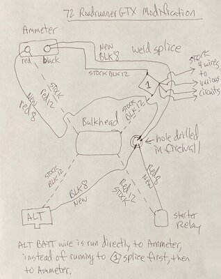
I'm posting a drawing I made of 72RoadRunnerGTX's modification that he did to his car (which I assume is a 72 RoadRunner GTX). My drawing shows factory wires that would be removed as dashed lines. Wires represented as solid lines are either newly added or stock that remain after the 72GTX modification.

What ramifications, if any, result from running a wire straight from the Alternator to the the Ammeter gauge? By doing this, current runs from Alternator to the black post on Ammeter, then from there to Weld Splice #1. Makes me believe Battery is first in line to draw current, then secondarily the other circuits of the car. Battery is first priority to get juice.

Factory has current run from Alternator to Weld Splice #1 first, then from there to the Ammeter guage. Makes me believe other car circuits are first in line to draw current, then secondarily the battery (if there is any left to draw). Other circuits of car first priority.

Maybe either way, Alt to Ammeter or Alt to Weld Splice, makes no difference in the flow of current??

IMG_4432.jpg
 
If you don’t want to drill through the firewall you can drill a hole on the bulkhead connector below the bottom plug. There should be enough room and would be undetectable.
 
As a variant of 72GTX modification, I thought of retaining the stock 12 gauge wire for Alternator Black and Battery Red, but replacing the Packard 58 connectors for these two wires with Anderson Powerpole PP30 (rated to 30 Amps) connectors.

Remove the male Packard 58 connectors from the two harnesses, and crimp a Powerpole PP30 onto those two wires. Attach a Powerpole black and red plastic housing to each accordingly. Route red wire from Ammeter out hole in firewall, pull wire through hole into engine compartment with Powerpole PP30 crimped on end. After wire has been passed through hole, push connector into another red plastic housing. Do the same steps with the Black wire running from Welded Splice #1 through hole in firewall.

This way, with ease in engine compartment, you can disconnect these two wires at will, just like you can with the harnesses. No Packard 58 connectors for these two wires in harnesses or bulkhead disconnect. Those two spots remain empty.

It seems the real "potential" problem area is the Packard 58 connections, not the 12 gauge wire used in those circuits. It seems perhaps 8 gauge wire is overkill for those circuits..

Comments on this idea? Good idea? If so, why is it a bad idea?
 
One the other hand, I'm quite sure NONE of these MOPAR Wellborn cars that were auctioned off this past January, had any such "modification" performed on their charging circuits. An they all probably have the "factory" Packard 58 connectors intact. BUT, I'm also sure the wiring harnessess and bulkhead disconnect, in them, are NOT 50 years old either. So if the connections are NEW, then I wouldn't think they'd be burning up 6 months later..

https://www.mecum.com/auctions/kiss...-vehicles-from-the-wellborn-musclecar-museum/
 
Auto Transport Service
Back
Top