You are using an out of date browser. It may not display this or other websites correctly.
You should upgrade or use an alternative browser.
You should upgrade or use an alternative browser.
Wiring help for my 1970 Sport Sat
- Thread starter Moparfiend
- Start date
I assume that the Voltage Limiter was the 70’s analog of really jusy a 5V sorce for the gauges? They didn’t have solid state Drop Out Regulators or LDO’s right? Is my assumption correct here regarding the Voltage Limiter? Ultimately I am wondering if I can simply feed the pulsing 5V line with an LDO. Or at least test the gauges with a 5V source. I previously measured a low frequency <1V signal at the VL which without a scope can’t tell what the RMS value is.
Nacho-RT74
Well-Known Member
Limiter just feeds gas and temp gauges ( oil too in case of Rallye clusters )
On previous replies I already posted how to test gauges without VL ( cell phone charger, couple of 1.5 batts in series ). That's just to test if they work or not. For calibration, is easy as get some resistors to check high, mid and low readings and feed from a confirmed 5 volts source. Let me know if you want to get deeper on this.
Testing VL just will tell if works or not, but output can't be tested. USUALLY is hard to be out of range, they work or not, but is not common to be out of range. They are adjustable with the adjusting screw thought, but just having the tools.
It seems ammeter is working propperly marking discharge on every hazzard blink. That's how must be with engine off.
Do a favor to yourself and your car. Upgrade the alt with an alt able to feed around 45 amps at iddle. Stock 60s and 70s alts barelly are able to feed 20-30 amps iddling, and sure your car will miss the rest of load provided by the alt.
Last edited:
Thanks Nacho! Yes Ammeter is working. So the instruments run on 5V?Well the good news is I think I found the problem.
The bad news is its a lot of missing connections. Over the years and a lot of Bubbtization lines were cut and spliced and not connected correctly or not connected at all or respliced with the wrong color wire. I found multiple wiring issues at both the dimmer switch and headlight switch. It totally explains the isses I have been seeing. These are the points of distribution from the schematic.
Now in order to fix it I can get a new harness or try and splice in the missing and chopped wires.
A new harness sounds nice but all that routing inside the dash which has piss poor access sounds like a lot of work. I know its the right thing to do but if the wires look ok I will work to splice in the right wires and try to use the right colors as to maintain the schematics accuracy.
Hopefully this solves most of the problems.
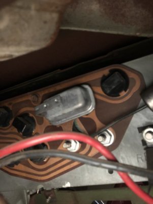
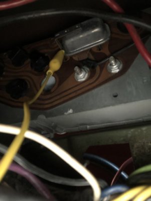
One question: where physically is the Voltage Limiter located? Is it on the PCB? Is it a metal can 3 prong device?
Nacho-RT74
Well-Known Member
just gas and temp gauges run on those pulsating 5 volts
So will the gas and temp guage run off of 5VDC?
Thanks yes I have a new alternator on my list to buy.
Thanks yes I have a new alternator on my list to buy.
Nacho-RT74
Well-Known Member
not just an alt, but an alt able to source everything, to sway the discharge readings on gauge. My suggestion, no less than 45 amps at iddle. 50 to 55 if A/C car
http://www.dodgecharger.com/forum/index.php/topic,33574.0/all.html
MaMopar applied some mods on charging system on fleet cars, to save the bulkhead from high loads, not using the alt and batt wires throught the bulkhead but a diff path throught the firewall. ( 72RR made that on his car as far I recall ).
If stock existant wires and terminals are still healthy you can keep them and run parallel paths ( which is what I suggest and made on my own car ) through firewall to release the stock ones from the loads.
Also check the ammeter gauge health. Tight studs to the internal shunt, good conditions isolation sheets ( inside and outside )
I used the rt-eng.com IVR4. It's a solid state pulsing 5V with a built in self resetting current limiter and all okay LED indicator.
I have used LM7805 regulator ICs with two 10uF filter caps on the input and output.
I have used LM7805 regulator ICs with two 10uF filter caps on the input and output.
Thanks Nacho I have AC and will probably get a 95A unit!
Bill thanks So are you regulating to a constant 5V or to an on off 5V at some magical duty cycle?
Bill thanks So are you regulating to a constant 5V or to an on off 5V at some magical duty cycle?
I used this on the Road Runner as it is a direct solid state pulsing 5V
https://www.rt-eng.com/index.php/RTE_limiter.html
I like the LED indicator that it is working and no short or ILIM detected.
You can also use a linear LM7805 and gut your old IVR. No over current protection, but it does work. I used this back in the day and had no issues (see section 9 in the link below)
https://www.allpar.com/history/mopar/electrical2.html
Nacho-RT74
Well-Known Member
you can build it up into the old case to make it cleaner and easy plug and play
http://www.moparts.org/Tech/Archive/elec/11.html
Rt Eng sate on table the pros and cons of each system. Well since they are the manufacturers of one, of course their unit is the perfect one LOL
http://www.moparts.org/Tech/Archive/elec/11.html
Rt Eng sate on table the pros and cons of each system. Well since they are the manufacturers of one, of course their unit is the perfect one LOL
Nacho-RT74
Well-Known Member
Lol... both posted the Moparts link. Didn't read it before.
and well of course, original replacements are still available
https://www.rockauto.com/en/catalog...cal,instrument+cluster+voltage+regulator,4885
https://www.ebay.com/itm/Instrument...e:g:ZM8AAOSw~XpZSEQc:rk:1:pf:1&frcectupt=true
and well of course, original replacements are still available
https://www.rockauto.com/en/catalog...cal,instrument+cluster+voltage+regulator,4885
https://www.ebay.com/itm/Instrument...e:g:ZM8AAOSw~XpZSEQc:rk:1:pf:1&frcectupt=true
Last edited:
- Local time
- 11:29 PM
- Joined
- Jan 14, 2009
- Messages
- 2,298
- Reaction score
- 1,926
- Location
- Shoreline, Washington
As mentioned, the RTE website has a good comparison of their product to the OE limiter and a solid state lineal 5-volt regulator (LM7805). Yes, the gauges will work fine on a constant 5-volt power supply. You will notice they will be slow to respond on initial power up. I’ve built and run a few LM7805 based VLs.
On the charging circuit wiring, yes, my preference is to rebuild the harnesses, replacing the 12-gauge charge wiring, with 8-gauge wire and by-passing the bulk head connectors completely for this circuit. No disconnects on this circuit. As mentioned, similar to the factory’s approach on their fleet vehicles with 65-amp alts at the time. It is more labor intensive than the parallel approach but way cleaner IMHO. BTW, the factory was aware of bulkhead connector-charging circuit issues early on. There was large C-body recall in the seventies that involved adding a parallel wire run from the alternator output stud to the “Batt” fuse box spade. How do I know? In my time working at dealers then, I probably installed hundreds of them, paid like .2 of an hour or something stupid, if you took the time to move the car into the shop, you were already upside down. Did most of them where ever I found them parked.
On the charging circuit wiring, yes, my preference is to rebuild the harnesses, replacing the 12-gauge charge wiring, with 8-gauge wire and by-passing the bulk head connectors completely for this circuit. No disconnects on this circuit. As mentioned, similar to the factory’s approach on their fleet vehicles with 65-amp alts at the time. It is more labor intensive than the parallel approach but way cleaner IMHO. BTW, the factory was aware of bulkhead connector-charging circuit issues early on. There was large C-body recall in the seventies that involved adding a parallel wire run from the alternator output stud to the “Batt” fuse box spade. How do I know? In my time working at dealers then, I probably installed hundreds of them, paid like .2 of an hour or something stupid, if you took the time to move the car into the shop, you were already upside down. Did most of them where ever I found them parked.
Last edited:
Tested the fuel gauge with a 5V source and sure enough its ok. It moved slowly to full.
Well then I yanked the VL and bench tested it and got what I thought was a functional result. I used a 12V source and got the unit to blink. I suppose this result is satisfactory since I was trying to figure if it was close to a 40% duty cycle.
The big problem I have now is re-inserting blind in the back of the dash while keeping the capacitor pluged in the hole. I tried a bunch of times no dice.
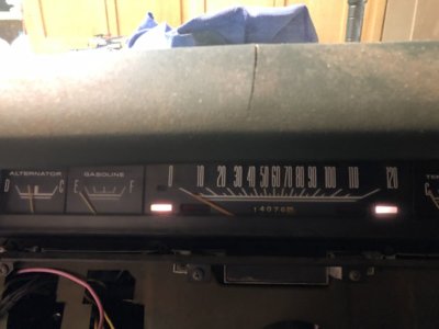
And I still dont know why the guages don’t work lol.
Ok got that sucker back in what a PITA.
Nacho-RT74
Well-Known Member
On the charging circuit wiring, yes, my preference is to rebuild the harnesses, replacing the 12-gauge charge wiring, with 8-gauge wire and by-passing the bulk head connectors completely for this circuit.
I kept the stock alt wire allowing to keep sourcing the main splice from both sides and not just from ammeter stud. This will double the wire gauging to it.
There was large C-body recall in the seventies that involved adding a parallel wire run from the alternator output stud to the “Batt” fuse box spade. How do I know? In my time working at dealers then, I probably installed hundreds of them, paid like .2 of an hour or something stupid, if you took the time to move the car into the shop, you were already upside down. Did most of them where ever I found them parked.
Thats a good one!
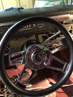
Ok was able to get the turn signals and horn on my steering wheeewirking. The GT Grant is a poor design as it shorts out and needs an isulater on the cap to function correctly.
Still no temo and oil pressure gauges. The sensors are wired correctly in the engine compartment. I am wondering if I can measure the viltages at the sensors. I know its that funky VL output. I suppose a 12V bulb to ground could be used to see if it switches on off like on the pwb.
Picture of my wheel

Similar threads
- Replies
- 17
- Views
- 981


