• When you click on links to various merchants on this site and make a purchase, this can result in this site earning a commission. Affiliate programs and affiliations include, but are not limited to, the eBay Partner Network.

Wiring help for my 1970 Sport Sat

A few different configurations for how the voltage limiter mounts/connects, on most a standard clusters it is plugged into the PCB. Three connections, ground, switched 12 volts, and pulsating output that averages about 5 volts.
Plymouth-Dodge-Roadrunner-Coronet-Rt-Dash-Cluster-Voltage.jpg
 
A few different configurations for how the voltage limiter mounts/connects, on most a standard clusters it is plugged into the PCB. Three connections, ground, switched 12 volts, and pulsating output that averages about 5 volts.
View attachment 719079
Thanks 72RR wow a picture and all! Your awesome man! Yes thats the device I thought it was. Can I probe for voltage on the component top side of the PCB for voltage? I want to verify that it’s working but its way up in the dash. Is it soldered in or can I pull it and DC test it on the bench with my 12VDC supply and DMM?
 
Should pull out. Not sure what you will see with the DMM, likely pulsating 12 volts on the output if its working.
There are also several solid state replacement options now if it doesn’t work.
 
You can check is getting pulse out to the gauges but will never check for the propper voltage because thats adjusted with osciloscopy. Its a RMS voltage output based on pulses as mentioned by 72RR made by a bimetallic piece inside.

6.jpg


It can be checked with a test light or an analog multitester waiting for voltage pulses, but never with a digital multitester due the samplig rate of digital tester will never meet with limiter pulse. As far you gets pulse from it, you can tell is good. You can test a dozen of limiters and will find each one pulses at diff rates. Is about average voltage output based on time and speed of pulses

BUT NEVER test the gauges/cluster WITHOUT a good ground arriving to the limiter. The bimetallic piece remains with points closed. It heats with keyed 12 volts source and the ground. If is not grounded, the points will remain closed and will allow the full 12 volts to gauges. If senders are conected, the needle could speed out passing out the max reading untill burn out the coil into the gauge ( which is a coiled bimetallic sheet too )
 
Last edited:
Just incase some stumbles upon this thread here is a good description and test method for this crude voltage limiter device.

 
Yeap... I have seen it several times, althought found that after I already tested mine LOL. There you have the science on this. That's actually for rallye cluster on 71/74 and several other kind of cluster where is not plugged into a PCB. The 3 prongs are diff than the one plugged into PCB. Ground doesn't get a prong where to get plugged but on the attaching screw on bracket. Some limiter models gets a prong on bracket to get a wired ground reinfocement ( 71/74 B rally is one of them ). The U shapped prongs on the video one are just to get the noise supression condenser attached to the same output. PCB ones gets the condenser inserted at the same time and locaton than Limiter
 
Last edited:
Yeap... I have seen it several times, althought found that after I already tested mine LOL. There you have the science on this. That's actually for rallye cluster on 71/74 and several other kind of cluster where is not plugged into a PCB. The 3 prongs are diff than the one plugged into PCB. Ground doesn't get a prong where to get plugged but on the attaching screw on bracket. Some limiter models gets a prong on bracket to get a wired ground reinfocement ( 71/74 B rally is one of them ). The U shapped prongs on the video one are just to get the noise supression condenser attached to the same output. PCB ones gets the condenser inserted at the same time and locaton than Limiter
If I was to replace it I would get the solid state. I see no reason to retro in a bimetallic technology like that.
 
I have around 4 original kind replacements for my car LOL, but a friend of mine gave me as present because I have helped a lot, one of the solid state ones ( RTE ) that mostly sure will use. Will change the housing though, because the RTE doesn't have the prong on bracket for the ground reinforcement.

180790426_mopar-71-4-road-runner-gtx-satellite-charger-dash-.jpg
 
Last edited:
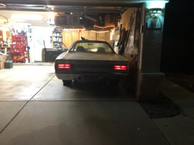
Well made some fast progress on the exterior lighting. I now have tail lights and side markers. The pink supply was not connected and was changed to a black lead. There are a lot of disconnected wires and connectors still. I have all the correct wire color stock and will fix that wire color to match the schematic.
I didn’t have brake lights but found my ground us ok but supply again is not there (pink wire issue again). When I hot wired the brake switch white wire I got the brake lights working. So I need to see whats up on that circuit.
Will post more as I move on to the gauges which are not working.

E632CA2F-DD38-44F5-B30F-B35D635F3BD1.jpeg
 
Last edited:
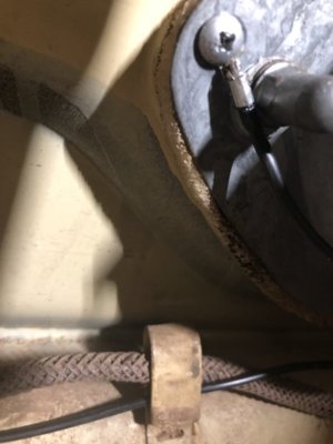
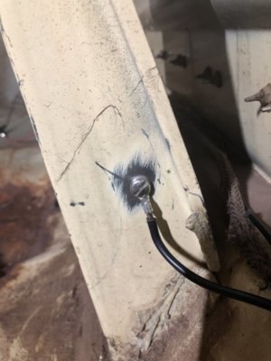
Well as I dig I find more and more issues. The good news is I am solving the mysteries as I go. The tail lights and markers are good not as well as the brake lights. I did have a problem with the brake lights. One side dimmed when I pressed on the brake. I added a ground strap to both rear light bezels and now both are brighter and equal. Here is that ground strap. Next up are the gauges then turn signals and horn. Bubba really messed up my new engine harness cutting wires. So the old bubba and nee bubba must be related. My lesson is NEVER let anyone work on my cars again. They just don’t give a crap like the owner.

743AA5D9-67A3-4BB4-A4A1-7F180F08EA94.jpeg ECA26683-372A-470B-82A6-EF0C2E3DA918.jpeg
 
Last edited:
And yes all my connectors are soldered.
 
Question: if my oil dummy lights up upon normal start can I assume the Voltage Limiter is working??
 
Whats a good starting point for my instruments?
 
Verify the limiter/cluster is grounded, and switched 12volts at the input to the limiter, ground the signal side of the gauge, look for gauge movement. If so, move to the senders, ground the leads- check for gauge movement.
 
Last edited:
Verify the limiter/cluster is grounded, and switched 12volts at the input to the limiter, ground the signal side of the gauge, look for gauge movement. If so, move to the senders, ground the leads- check for gauge movement.
Thanks 72RR. Should I be doing this with the instrument cluster removed? I am having a hard time getting at the guages and VL.
 
you can test gauges itself with any 5 volts source available... call it cell phone charger or whatever similar. Even dual 1.5 batts in series ( 3 volts is pretty much enough ). Feed both gauges studs ( either way will work ) and that will tell you if gauges are in good conditions with just check if needle moves
 
In that case I would start at the sender leads where they are easiest to get to first. Ground the sender leads at the senders, work your way towards the cluster. Start with fuel sender lead at the kick panel 6-way, dark blue wire, gauge response when grounded?

Ground the violet wire at the temp sender, gauge response? go to the bulkhead connector, ground it there.
no response on both gauges, problem is likely in the cluster, gauges or limiter
 
( except amm... amm gets its on life handling the power loads between batt and alt )
 
Auto Transport Service
Back
Top