• When you click on links to various merchants on this site and make a purchase, this can result in this site earning a commission. Affiliate programs and affiliations include, but are not limited to, the eBay Partner Network.

71 Road Runner Restoration Started

Welcome back Louis!
I love seeing cars torn down and put together the right way!

Thanks Don. Like you I absolutely hate to do something that is not correct. When I do something and it's finished, I know that everything in my power was done to make it right. Otherwise, I wouldn't even attempt at it. Take care buddy. It's good to be back.
 
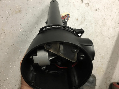
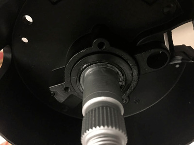
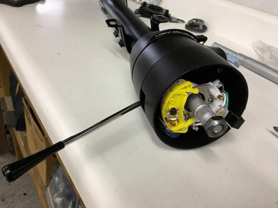
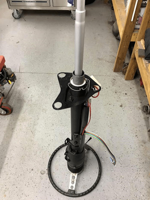
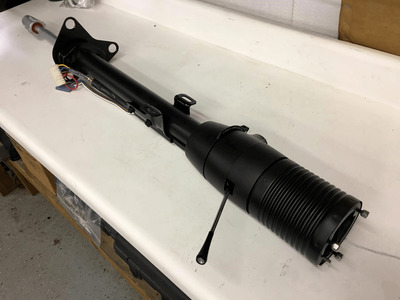
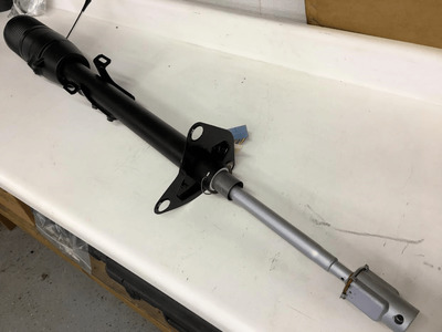
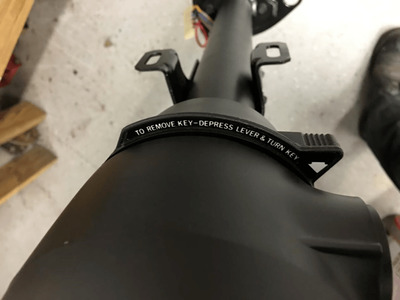
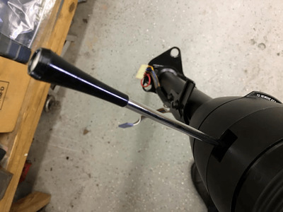
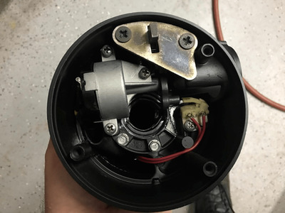
Here's some pictures of the steering column after I restored it. I basically disassembled everything, and glass beaded most of the parts down to clean bare metal. Some things I soaked in a cleaning solution to remove the grease. The individual parts were then repainted in the correct colors. Once it the paint was dry, I started reassembling everything. Then I replaced the steering shaft coupler internals, (where it connects to the power steering gear box) , added new electronic parts, (ignition switch and turn signal switch), replaced the upper steering column bearing with a new one from Chrysler, plastic lower shaft seal retainer, and added a new chrome turn signal lever, also from Chrysler. The original "Key in buzzer" electronics were cleaned and reused.

Steering column restoration    1.png Steering column restoration    2.png Steering column restoration    3.png Steering column restoration    4.png Steering column restoration    5.png Steering column restoration    6.png Steering column restoration    7.png Steering column restoration    8.png Steering column restoration.png
 
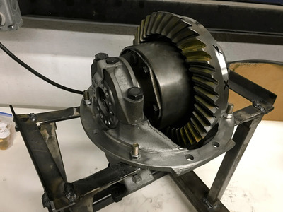
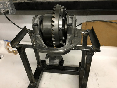
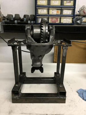
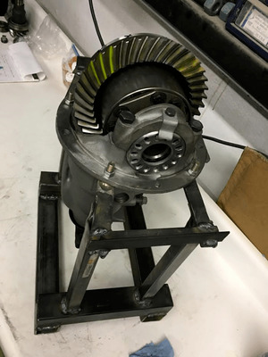
I rebuilt the 3.55 gear chunk. Originally this chunk had a set of 3.91's in it. I replaced them with a new set of 3.55's now. This is a 489 gear case and it now has a solid billet crush sleeve, in place of the original sheet metal one. I also added a new Detroit Locker unit in place of the original Sure Grip unit. I made the stand out of some scrap steel I had floating around in the shop. (the welds look horrible) the welder I was using at this time when I built this gear rack didn't get hot enough for a good penetration into the steel. This has since been rectified............ I still have the 3.91 gear set along with the original bearings, crush sleeve and 7290 large 10 spline U joint yoke that were installed with it originally, and I'm looking to sell it at a reasonable price. They are in great shape, but were simply too low of a gear for my liking. I saved them in the foam packing that the new gears came in for shipping. I'm pretty sure the 3.91's are a Richmond gear or another aftermarket performance gear set from the late 1970's or early 1980's. The Challenger this chunk came from was set up to drag race back then and had a 727 Torque flight in it.

3 55 gear set install   1.png 3 55 gear set install   2.png 3 55 gear set install   3.png 3 55 gear set install.png
 
Last edited:
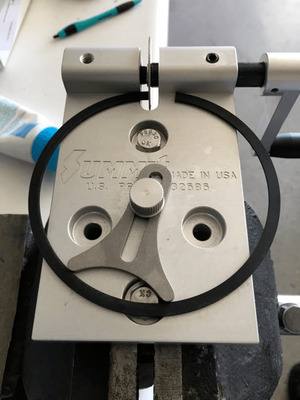
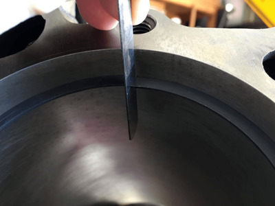
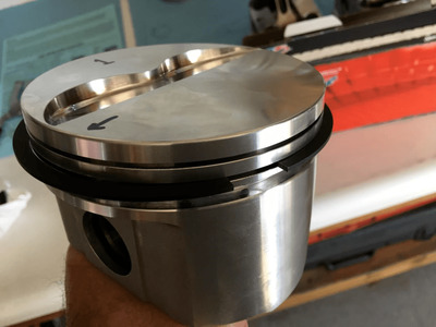
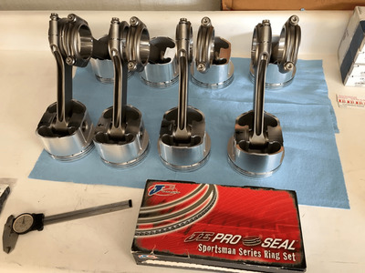
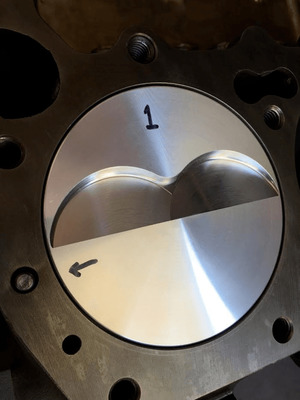
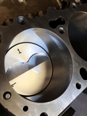
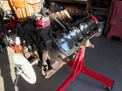
I started the engine short block assembly a while ago. I used a set of JE Pro Seal file to fit rings, and custom matched the rings for each cylinder.

file to fit rings.png file to fit rings   1.png file to fit rings   2.png file to fit rings   3.png file to fit rings   4.png
 
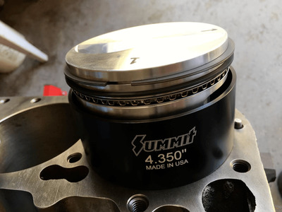
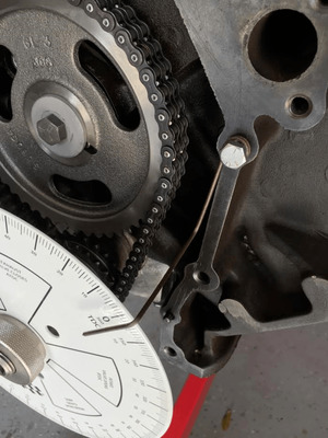
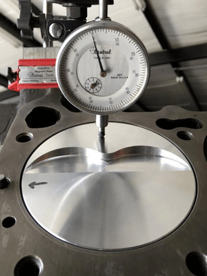
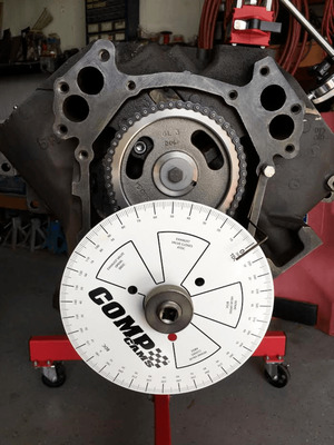
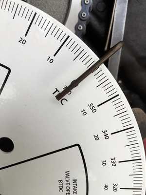
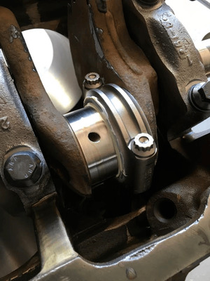
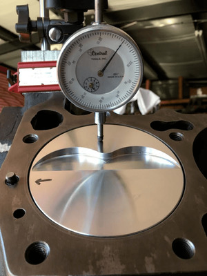
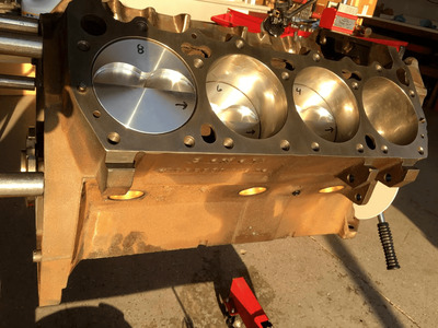
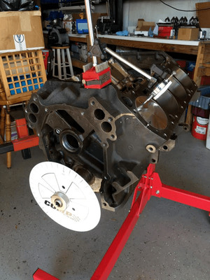
Once I was happy with how everything fit, I assembled the short block. Here's a few pictures of the process................... Afterwards I found the true TDC and got the degree wheel ready for the cam installation................... which is in the next set of pictures.

short block assembly.png short block assembly    5.png short block assembly    1.png short block assembly    2.png short block assembly    3.png short block assembly    6.png short block assembly    4.png short block assembly    7.png
 
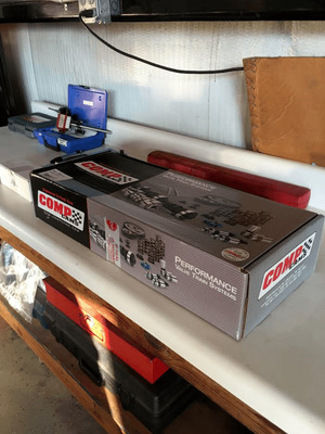
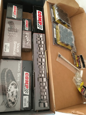
Here I am installing the cam and getting everything ready to degree it in...................... This is the initial assembly and will come back apart once more for a proper pre lube.

cam degree process   6.png cam degree process   7.png cam installation.png cam installation    1.png cam installation    2.png cam installation    3.png cam installation    4.png cam installation    6.png cam installation    5.png
 
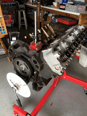
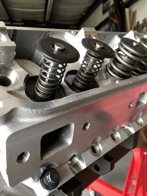
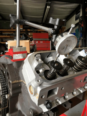
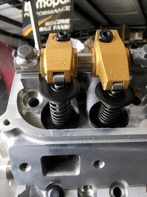
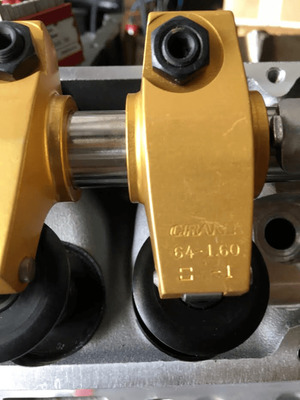
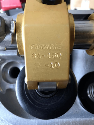
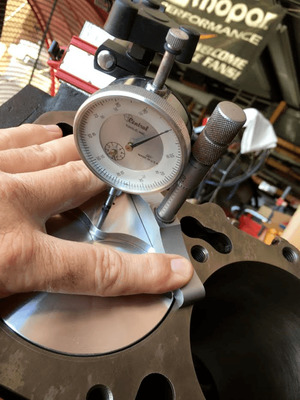
Then I started degree-in process of the camshaft. The first thing I did was to remove the valve springs from the #1 cylinder on one head. I replaced the springs with a set of test springs. Then I temporarily bolted on the 440 Source Stealth head. I'm using Crane 1.6 roller rockers on this one. A lot of clearances still need to be checked here. One thing I found out by doing this is that the push rod holes are way too small...................... I had to open them up quite a bit to ensure proper clearance.

cam degree process.png cam degree process   1.png cam degree process   2.png cam degree process   3.png cam degree process   4.png cam degree process   5.png
 
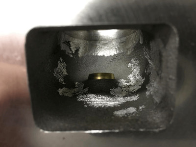
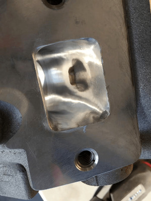
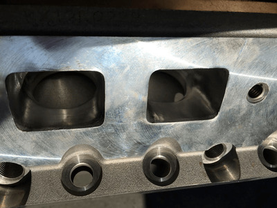
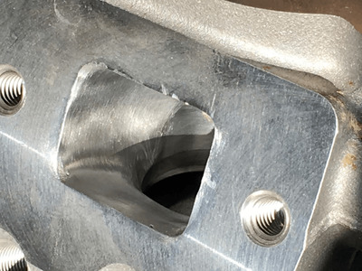
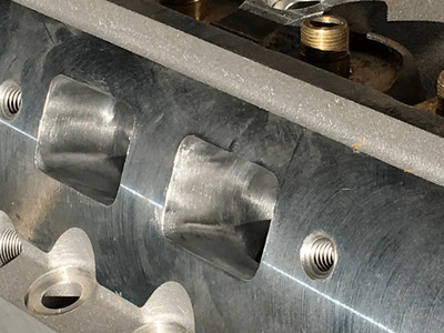
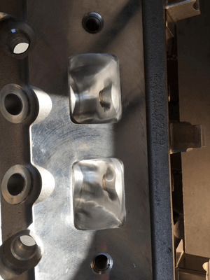
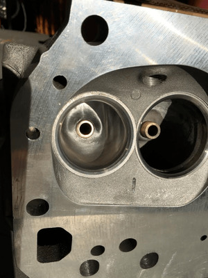
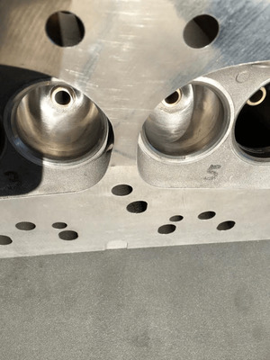
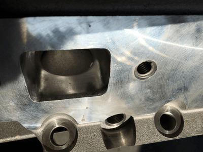
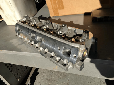
After studying the ports on the Stealth heads, I decide to clean them up just a little. The original intent was to simply knock off some of the excess casting "warts"................. This ended up being more work................... since I decided to go ahead and polish the exhaust ports as cast. I'm not changing any of the port design, I'm simply cleaning it up some. Hopefully this will help a little in the HP numbers. After I polished the exhaust ports I decide to knock the "warts" off the intake ports too. But so far I have left these ports in this state and not polished them. They have simply been de-burred.

This pretty much brings the engine build up to where I am at now. Once I get the spot welding done on the body, I plan on jumping right back in on the engine, getting it ready for the test run stand....................

Enjoy !!!!

Stealth head porting  7.png Stealth head porting  6.png Stealth head porting  1.png Stealth head porting  3.png Stealth head porting  4.png Stealth head porting  5.png Stealth head porting  9.png Stealth head porting  10.png Stealth head porting.png Stealth head porting  2.png
 
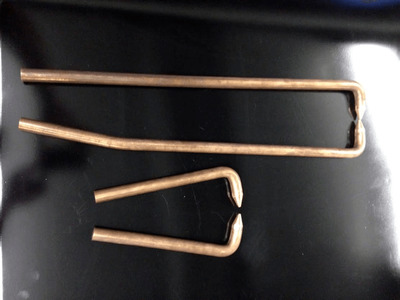
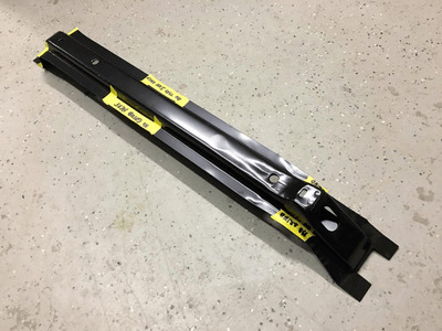
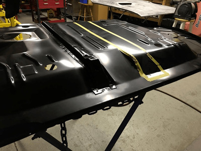
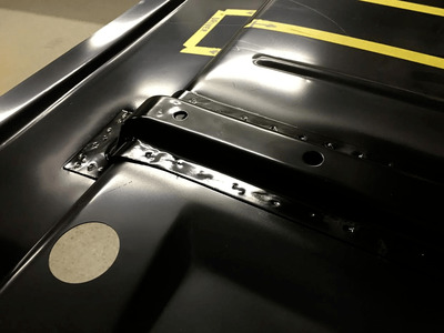
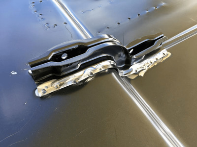
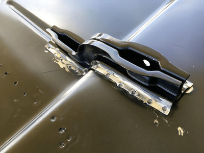
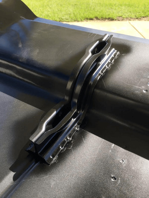
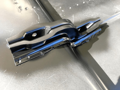
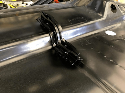
Tonight I spot welded one of the gas tank braces to the bottom side of the trunk floor pan. Prior to doing this, I had to swap over to the longer reach offset tongs. You can see them in this first picture.

The second photo shows what the gas tank brace looks like before it gets spot welded in place.

The middle picture shows the gas tank brace after it was spot welded against the trunk floor.

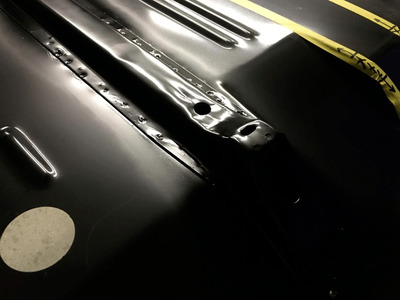
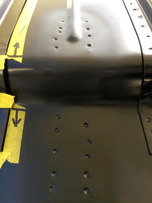
and finally the last two pictures show close ups of the spot weld details. Sorry but the lighting was poor and these pictures are not the best..................

Calling it a day. Comments are encouraged.

Gas tank brace spot weld 4.png Gas tank brace spot weld 3.png Gas tank brace spot weld 2.png Gas tank brace spot weld 1.png Gas tank brace spot weld.png
 
I'm trying to work on mine as well but have been delayed due to breaking my leg :(
 
I'm trying to work on mine as well but have been delayed due to breaking my leg :(

Wow that sucks.............. I have been there with various leg, foot and ankle injuries over the years, so I know what you are experiencing. I am very good at getting around on crutches........

Here's wishing you a speedy recovery.
 
Thanks 71airgrabberRR and everyone else wishing me a speedy recovery. Yea, it sucks but getting around good on crutches myself.
 
I am curious about the spot welder you have. Can you tell me about it?
I have wanted to get one but am a bit cautious about "learning how to use it" vs. the tried and true plug weld.
 
I am curious about the spot welder you have. Can you tell me about it?
I have wanted to get one but am a bit cautious about "learning how to use it" vs. the tried and true plug weld.

Don,
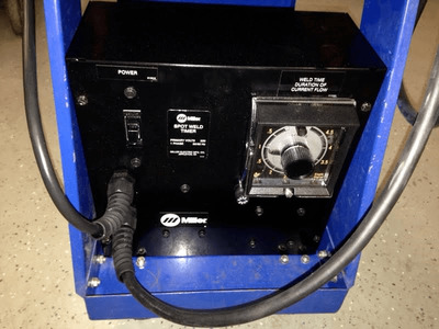
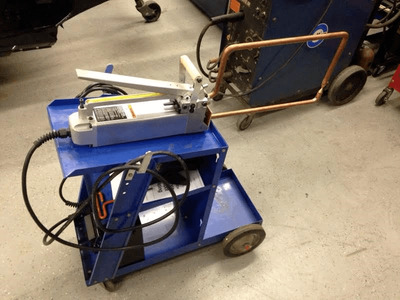
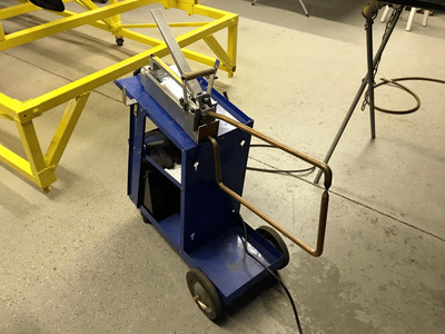
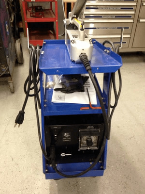
I have a Miller spot welder. It's a 220 Volt unit and I opted to pay a little more to get the one with a timer so I could make consistent welds. I had the blue cart left over from another old welder that I no longer have. I also purchased several different types of tongs to use in different locations on the car. These tongs are available in many configurations.

Initially I bought one from "China Freight". Never again will I buy anything from them.................... I had used it to weld in the new front radiator opening since I was upgrading from a 22 inch radiator to a 26 inch one................ I made about 15 - 20 spot welds with it and it quit working !!!!!! I tried to take it back, but since I didn't use it right away after I bought it, the warranty expired before I ever used it. It didn't matter that the thing crapped out on me only after using it once................ Don't waste your money there......................

Its really pretty simple to use since the spot welder has a timer on it. The timer goes from .01 seconds all the way to 5 seconds. The longer the length of time you set on the timer, the longer the current goes through the tongs creating the weld. I made a few metal coupons out of the same thickness sheet metal as my replacement panels, to try the spot welder out on before I used it on the car. While making some practice runs, I adjusted the timer until I got a good penetration. (I'm almost afraid that I may have the timer set just a little too long, and will back it off a fraction of a second). Then I tried to pry apart the spot welds from my experiment, and the actual metal ripped around the area that was spot welded. The welds themselves never broke loose.

As long as the metal is clean, and free of paint, all you have to do is close the tongs together and hit the switch to energize the unit. The timer does the rest and ensures that all welds are the same. The only down side is the actual unit that does the welding with the tongs is pretty heavy. It gets awkward at times. Another thing to watch out for is the metal you are welding together has to be making good contact with each other. If not, this will blow a hole through it, just like a torch would.

Overall it's very simple to use. It's quick and easy. Once your parts are spot welded together, your pretty much done. I do normally go back and grind off any excess flash spurs from around the spot weld, since these things are like razors and will slice the hell out of your finger tips later on when you are sanding on the car........... Ask me how I know this..............

Here's a few pictures of the spot welder I have. So far it has worked great (knock on wood). So far I have used it to rebuild a 1953 Chevy Truck Cab and sides of the bed for a friend of mine, plus the work I have done here on the Challenger. I wish I would have used one of these years ago. It's so simple and easy to use. Much easier in my opinion than plug welding with a MIG.

Hope this helps Don. Take care bud.................
spot welder 2.png spot welder 3.png spot welder 4.png Spot welder tips.png
 
Last edited:
Here's todays progress.....................
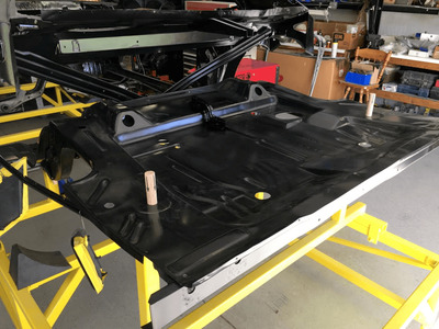
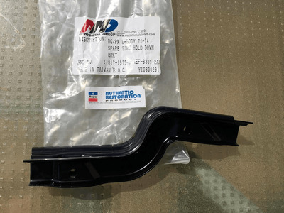
It's not much, but it's progress. I spot welded the spare tire hold down bracket to the trunk floor. Originally on my car, this part was held in place by a few crappy MIG welds from the factory. Half of the factory weld wasn't even on the part. Instead it was on the trunk floor. It must have been a Friday afternoon, or first thing Monday AM when they installed the part originally......................
Once I spot welded the bracket in place, I used a right angle grinder with a flap wheel to smooth out any burs that were caused by the spot weld process. These little burs are like razors. You tend to find them with your finger tips when you are sanding on your car........... blood usually follows soon afterwards. So I take care of them right then and there.

Then I gave the area a quick spray of black to help keep rust at a minimum.

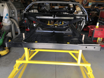
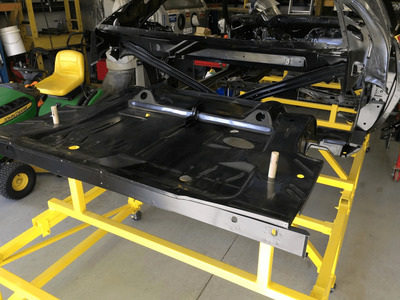
Finally I placed the trunk floor in position, and used the alignment dowels, to see how it will look once it's done and spot welded in place for good. Plus this way it isn't sitting on the shop floor (or taking up excess room on a body stand), and it helps to keep it safe from accidents.

Tomorrow I hope to get the other gas tank brace spot welded in..................
Until then, Take care.

spot weld  1.png spot weld  2.png spot weld  3.png spot weld  4.png spot weld  5.png spot weld  6.png spot weld  7.png spot weld  8.png spot weld  9.png spot weld.png
 
Today while I was waiting for some primer paint to dry on a hood that I am painting for a friend, I managed to get the other gas tank brace spot welded on the trunk floor.

Here's a few pictures..............
Then I sat the trunk floor back in place on the rear frame rails............... Hopefully soon this will be installed.
Spot weld trunk floor   1.png
Spot weld trunk floor   2.png
Spot weld trunk floor   3.png
Spot weld trunk floor.png
Spot weld trunk floor   4.png
 
I've been busy with another major project, so I haven't been able to do much on my Challenger................ However, the project is done now.
So I went back to work on the Challenger.
FullSizeRender.jpg


and started spot welding the rear "Under the Seat" Floor pan in place.
IMG_8847.JPG


This is how it looks right now.............................
IMG_8848.JPG


So far it's fitting like a glove. Tomorrow I hope to finish up the installation, and hopefully I can start on the trunk floor too.

IMG_8849.JPG

Thanks for following along.

Comments are encouraged.
 
IMG_8866.JPG


Today was a great day out in the shop....................... I was able to complete the spot welding of the "under the seat" floor pan on the Challenger. The spot welder gets rather heavy, so I came up with this "improvised" method to help support the weight. These bungee chords made things a whole lot easier............
IMG_8874.JPG


Here's the new "under the seat" pan after I de-burred the spot welds...........
IMG_8875.JPG


and the same area after I sprayed on some black to keep it from flash rusting....................
IMG_8878.JPG
IMG_8880.JPG


I'm not bragging, but I think it turned out pretty good.....................
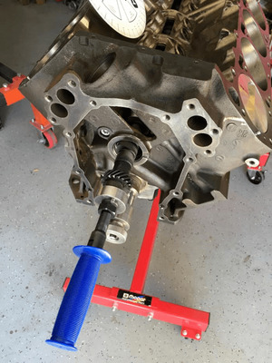
IMG_8881.JPG


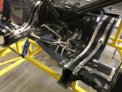
This is how the car look from underneath now with the new sheet metal welded in place.......................
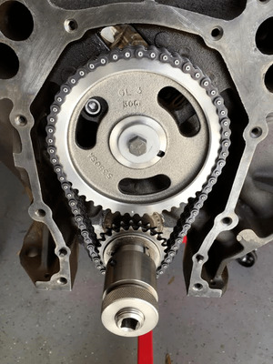
IMG_8882.JPG

IMG_8883.JPG


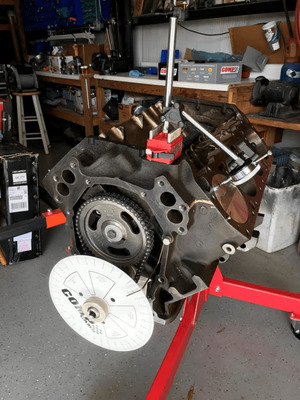
Hopefully tomorrow I can get the trunk floor welded in position.....................
 
Auto Transport Service
Back
Top