bought mine in 2017 early and it does not.
You are using an out of date browser. It may not display this or other websites correctly.
You should upgrade or use an alternative browser.
You should upgrade or use an alternative browser.
Borgeson 800126 Install 1971 Charger
- Thread starter MoparGuy68
- Start date
MoparGuy68
Well-Known Member
As I recall, there are 4 master splines on the output shaft. The pitman arm can be mounted in one of 4 positions. Each 90 degrees apart. So once you have the box centered, only one of those 4 positions will be correct. The correct position will have the center link end, inline directly aft of the output sector shaft.MoparGuy68; Just curious. Does the Borgeson box utilize a master spline; that is, one spline thicker than the others so that it locates the pitman arm?
The input shaft, and Bergman coupler do not have any master spline. So it is important you center the box before attaching the coupler. I found it tough to find exact center. Though, if mine is off center it should only be by +/- one spline tooth. After putting everything back together underneath, when I have the steering wheel centered, the wheels are very slightly turned toward the driver side. Hopefully, some minor tie rod adjustment during alignment should fix that.
MoparGuy68
Well-Known Member
Latest update on the Steering system. I'm posting everything in this thread that I had to do to the car to complete this steering swap. And no, I still don't have a working Borgeson steering system or drivable car yet..
The HP exhaust manifolds are mounted on the engine. Had custom head pipes fabricated and installed yesterday. Months later, I now have a closed exhaust system that clears the Borgeson steering box, yeay!
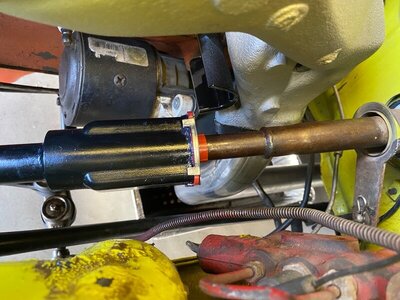
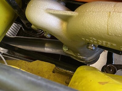
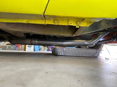
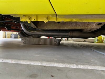
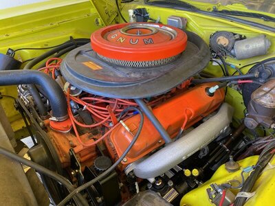
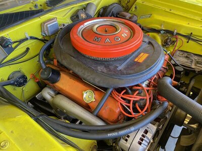
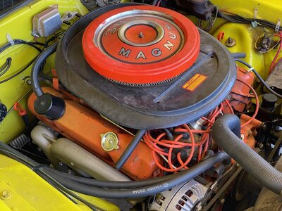
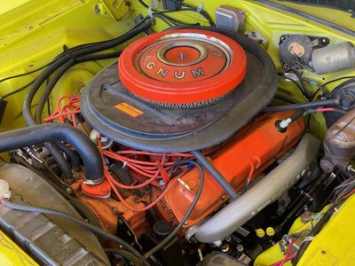
The HP exhaust manifolds are mounted on the engine. Had custom head pipes fabricated and installed yesterday. Months later, I now have a closed exhaust system that clears the Borgeson steering box, yeay!


MoparGuy68
Well-Known Member
Some photos of the car being winched up onto a flat bed truck to be hauled back home from the muffler shop. Performance Muffler, in Phoenix, fabricated and installed the head pipes. They also fixed the misalignment of the machine gun tips, so I now have decently aligned tips. Before the passenger side stuck out too far and one tip was noticeably lower than the other.
Customers and employees at the shop helped push the Bee into position to be winched onto the truck. So many people keep telling me what a beautiful car I have and how great it is. I then tell them, yeah it looks nice, but it doesn't run or drive and has so many things that need to be fixed.. So, so many things wrong with this car.. This is PROJECT car. I bought a nice looking project car, NOT the driver I thought I was buying.
I have to admit it looked damn cool going down the freeway on the flat bed truck. I followed it all the way home. I was fantasizing about actually being able to drive it on the freeway. First time it was out of the garage in over 4.5 months..
They can't see.. What you mean to me.. What you mean, to me, my little PROJECT TRAILER QUEEN BEE!
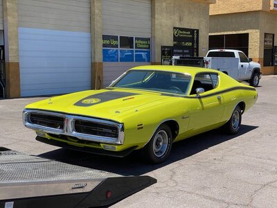
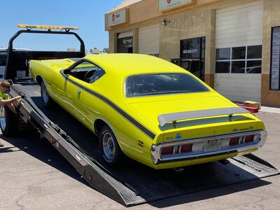
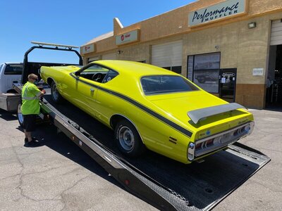
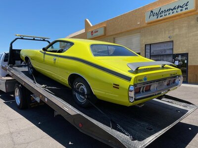
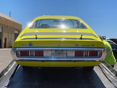
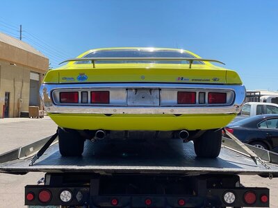
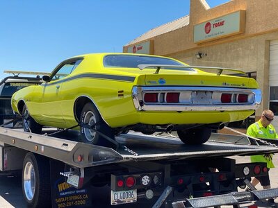


MoparGuy68
Well-Known Member
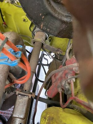
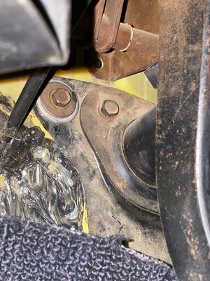
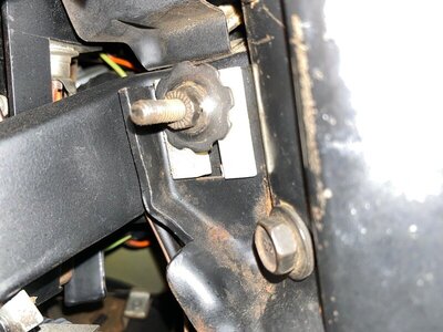
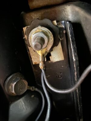
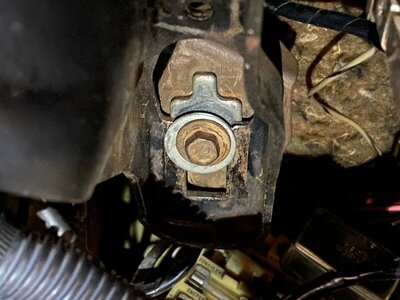
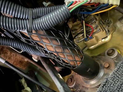
The lack of clearance between the steering column shaft and the column shift linkage sleeve is giving me grief!
I tried to solve this problem a couple months ago, apparently failing to do so. Used a bottle jack to raise the column assembly as high up as it would go, before bolting the floor bracket to the floor pan. I CANNOT raise it any higher.. I have NOT been able to get that shaft centered inside the column shift sleeve. At one time I could fit a screw driver partly between the top of the column and the sleeve. After moving the car to the muffler shop and back, I now see that the column has moved closer to the sleeve. There is almost no clearance now.. The end tip of a small flat head screw driver will barely fit in there now. There is a huge gap at the bottom and none at the top.
How the hell do you increase the clearance between that sleeve and the column?? If I leave it the way it is now, I know it is going to start rubbing and making contact when the steering wheel is turned or the column shift lever moved.
Another issue is the round hole in the column (near the coupler attaching end) is only at best 1/4" to 5/16" away from the firewall end of the Bergman coupler. The stock coupler had the same distance before I started this "swap". Factory service manual says it should be 13/16" and so does Bergman in his instructions. If I move the column (where it mounts under the dash) further back to get the 13/16" spec, then the floor plate is so far away from the firewall, it cannot be bolted up to the firewall..
I've attached photos showing the position of everything. I'll also send these photos to Bergman to see what he has to say.
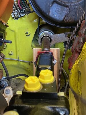
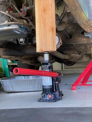
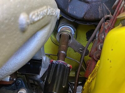
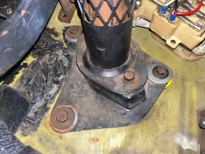


You are persistant! It will be worth it in the end. These gear boxes are a really nice upgrade from stock.
The input shaft does not utilize a master spline. I'm not sure why Borgeson never did that. The centering is like 1.870 turns each way from center to lock.
You can tell when the box is centered, the pitman will be in line front to back from the box to the center of the joint at the center link. Also, for god sakes put the hammer and pickle fork down. OTC makes a tool set for a $100 that is all pullers. You can separate any joint without ruining the boots, your car or your hands!
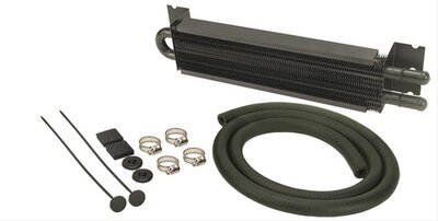
For the others, here is a shot of the cooler I sell. It has integral brackets that make mounting look factory.

MoparGuy68
Well-Known Member
You are answering someone else's question about the master spline. It was coloradodave who asked that.You are persistant! It will be worth it in the end. These gear boxes are a really nice upgrade from stock.
The input shaft does not utilize a master spline. I'm not sure why Borgeson never did that. The centering is like 1.870 turns each way from center to lock.
You can tell when the box is centered, the pitman will be in line front to back from the box to the center of the joint at the center link. Also, for god sakes put the hammer and pickle fork down. OTC makes a tool set for a $100 that is all pullers. You can separate any joint without ruining the boots, your car or your hands!
For the others, here is a shot of the cooler I sell. It has integral brackets that make mounting look factory.
View attachment 969501
Do you have any input or suggestions on the steering shaft / column shift sleeve alignment, or my issue of not being able to get anywhere near the 13/16" factory distance between coupler and hole in column? I posted photos showing the lack of clearance between the steering shaft and column shift sleeve at 12 O'clock position.
GMachineDartgt
Active Member
I’m going to assume you’ve loosened the firewall plate in your attempt to center the column shaft within it’s housing. The photos don’t show the plate maxed out. The holes under the silver washers are pretty large.
How are into the coupler is the shaft?
How are into the coupler is the shaft?
MoparGuy68
Well-Known Member
I’m going to assume you’ve loosened the firewall plate in your attempt to center the column shaft within it’s housing. The photos don’t show the plate maxed out. The holes under the silver washers are pretty large.
How are into the coupler is the shaft?
Yes, I completely loosened all 3 bolts that go through the firewall plate. I also had the 2 mounting nuts a little loose, that secure the column to the underside of the dash, and the bolt on the rear right that secures under the dash as well. After doing so I raised the column shift sleeve up as FAR as it would go with a bottle jack (see the photos I posted above, that clearly show what I did with the bottle jack).
While it was jacked up, I then tightened EVERYTHING down, especially torquing down the firewall plate bolts FIRMLY. I could only tighten the nuts under the dash so much or I would crush those flimsy plastic shim/spacer things. After removing the bottle jack, that sleeve dropped down a bit closer to the column shaft, but I could still slide a screwdriver between the gap a 12 O'Clock.
After the car was winched up on a flat bed and hauled to the muffler shop and back, I can now only slide a thin piece of paper or the thinnest edge of a flat head screw driver tip, just barely between the gap. The gap is now almost closed.
It seems to get the column raised any higher would require raising the attachment points under the dash, or removing the plastic shim spacers that are supposed to be between the nuts and the dash frame where the studs protrude through. The whole engineering design of the column mounting seems lousy to me. It looks like it's "cobbled" together in a primitive fashion. As in bolt the **** together and pray it doesn't fall apart.
The round hole in the column is 1/4" to 5/16" maximum aft of the firewall rear edge of your Bergman coupler. Not even close to the factory 13/16". I have photos before I started this swap showing the same 1/4" to 5/8" spacing with the stock coupler, before I touched a thing on this car. So about 1/2" further into the coupler than factory specifications.
I think the input shaft of the stock steering box is a little lower than the Borgeson, as the gap at 12 O'Clock was still small, but not as small as it is now with the Borgeson.
This swap has been nothing but problem after problem for me on this car. I'm frustrated with the whole thing. And frankly the only thing good I can say about this "Super Bee" is it looks nice from the outside, other than that there is nothing "Super" about it. Mechanically and electronically it is a mess. The latest thing is now the power windows have stopped working, the driver side is stuck in full down position and the passenger side is stuck full up, so it had to be hauled with one window up and one window down on the freeway.
Since you say there was a small gap at the top of the column even with the old box, it sound like there is something else going on here.
Regardless, you can try adding a 1/8" shim at the top bolt of the box to tip the input down slightly. This may help. The column mounting isn't bad from a design stand point. It allows lots of adjustment, its collapsible and its break away for accident protection.
Regardless, you can try adding a 1/8" shim at the top bolt of the box to tip the input down slightly. This may help. The column mounting isn't bad from a design stand point. It allows lots of adjustment, its collapsible and its break away for accident protection.
MoparGuy68
Well-Known Member
I'll send you an email regarding my theory of why my column may be inserted further than stock into the coupler. Maybe that might have something to do with the small gap at top too..Since you say there was a small gap at the top of the column even with the old box, it sound like there is something else going on here.
Regardless, you can try adding a 1/8" shim at the top bolt of the box to tip the input down slightly. This may help. The column mounting isn't bad from a design stand point. It allows lots of adjustment, its collapsible and its break away for accident protection.
Happy to listen. There is a spec of the suggested depth the little shoes. If the are in to far, it will bind on the column shaft.I'll send you an email regarding my theory of why my column may be inserted further than stock into the coupler. Maybe that might have something to do with the small gap at top too..
MoparGuy68
Well-Known Member
Going to attempt to fill the PS system and bleed the air from it this weekend. Will be doing this by myself, so I asked Peter, via email, what the best way to do it solo is?
He said "You can fill the system, and remove the coil wire. You can crank the engine and the fluid will be pulled into the system. If you jump the starter relay, all can be done from underhood".
So based upon what he said, and that I also need to bleed the air from the system, this is what I'm going to do tomorrow.
1. Fill Reservoir to between cold and hot fill lines (yes, my PS dipstick has a cold and hot fill line)
2. Remove the coil wire.
3. Connect my 30+ year old remote starter switch (which I haven't used in 30+ years) to the starter relay. Connecting one lead of the switch to the Relay's BAT terminal, and the other lead to the SOL terminal.
4. Turn ignition switch to run position, without cranking starter. Transmission in PARK. Wheels chocked.
5. Press button on my remote switch and crank engine for a few seconds. Then release button to stop cranking.
6. Check fluid level, and add as necessary.
7. Repeat step 6 until the fluid level no longer goes down and it is at cold fill line.
At this point the system should be filled to capacity with some combination of fluid and air..
Bleeding procedure is next.
1. Jack car up and put jack stands under lower control arms.
2. Re-connect coil wire
3. Press button on remote switch to crank and start engine. Engine is running at idle speed.
4. Check fluid to ensure it does not get too low. Add as required.
5. Reach into car and slowly turn steering wheel from lock to lock once.
6. Check fluid. Look for air bubbles. Add fluid to maintain level.
7. Repeat steps 5 & 6 until no air bubbles appear in the reservoir and fluid level is between cold and hot fill lines.
8. When engine has reached normal operating temperature, check that fluid level is not higher than hot fill line.
I have a PS cooler so hopefully coolant won't get too hot and shoot out of the reservoir as the fluid heats up and air escapes. I'm nervous about this whole filling and bleeding procedure, as I've NEVER done it before. It shouldn't be like the radiator as if the reservoir cap is off, it will boil and erupt like the coolant did, right?? My Mopar steering experience is with MANUAL steering, no pumps, no reservoirs, no belts, no leaky gearboxes, no coolers, just your arms, a steering wheel/column and a simple gearbox that isn't under high pressure.
If any of these steps seem horribly wrong, maybe someone could let me know. As I'll check this thread again before I start this task..
66 Sat
Well-Known Member
Sounds ok to me. Mine was reinstalled and filled before the engine went in so when I started the car to run the cam in, it burped power steering fluid everywhere, helped by the big fan blowing on the engine.
Your method seems pretty thorough, just have some towels handy in case any fluid gets ejected.
Your method seems pretty thorough, just have some towels handy in case any fluid gets ejected.
MoparGuy68
Well-Known Member
I do have one concern with my stated method above. Will all the cranking with the coil wire disconnected flood the engine with gasoline?
This past December I cranked the engine about 25+ times, which included pumping the accelerator pedal once or twice before each crank. This was when trying to start the engine when the coil was disconnected (and me forgetting that it was). This resulted in a badly flooded engine that ran extremely rough, when I eventually got spark to the cylinders.
If I crank several times with no spark, without pumping the accelerator even once, will I still end up flooding the engine?
I've already put fluid in the reservoir and turned the pulley by hand, with the belt disconnected. I turned the pulley about 20+ revolutions and the fluid level did NOT go down at all, at least that I could visually see. So, I don't know how well this cranking with no spark is going to work..
66 Sat
Well-Known Member
You're overthinking all this. Just fill the pump with oil and start the engine. Turn the wheel slowly side to side to expel any air, check the level, and go for a drive. Did your bleeding instructions come with the new box?
MoparGuy68
Well-Known Member
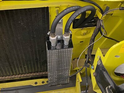
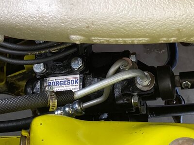
Peter asked to see photos of my Borgeson system installation, so I'm posting photos of my completed system install here.
I've included my starter relay, and the remote switch I plan to attach to the relay, to allow control of the starter motor, while I'm standing alongside the driver fender. Have had the switch for over 30 years and it's actually marked "Made in USA". I'm certain nothing like this switch has been made in USA in decades..
Cooler is a Heavy Duty Transmission cooler, with 3/8" threaded pipe fittings that came from Perma-Cool. Peter was out of stock of his cooler at the time I ordered this one. I have 3/8" hose barbs screwed into the fittings that are sealed with Permatex High Temperature Thread Sealant (rated for 400 degrees F). Return lines are 3/8" PS hose.
Car has a goofy radiator set up. Fender tag says it originally had a factory 26" radiator. It currently has a 26" radiator custom mounted to a 22" core support. I mounted the Trans/PS cooler using two of the 22" threaded holes on the driver side of the core support. Whoever installed the 26 radiator made 4 new mounting holes in the core support. I believe this car had a frontal impact at some time during its life, and the damaged 26" core support was replaced with a 22" support. There is no VIN number to be found anywhere on the core support, so maybe it is repro.. They converted from standard headlights to concealed headlights with inside hood release, probably at the same time.
Haven't attempted to fill the system yet. Had to charge the car's battery this morning, which took 2.5 hours (the charging system is not working, and will need to be troubleshooted after I get the steering system filled and bled..)
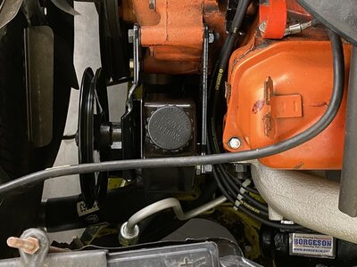
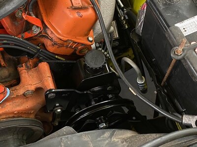
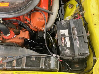
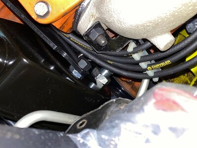
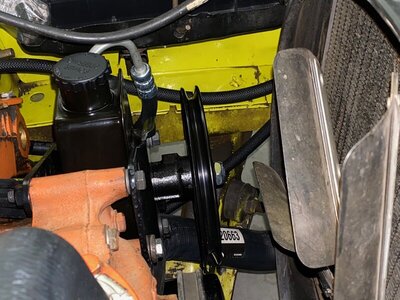
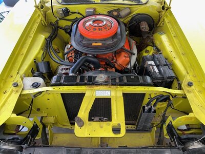
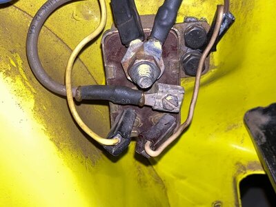
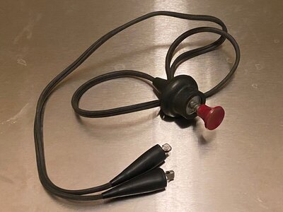


All looks good, except the cooler should be mounted so the hoses come in and out of the side.
MoparGuy68
Well-Known Member
Why should the cooler be mounted sideways? What’s bad about mounting it vertically like I have it?All looks good, except the cooler should be mounted so the hoses come in and out of the side.
The current position allowed me to utilize the existing unused 22” mounting holes, doesn’t block airflow from the radiator, doesn’t require any mounting directly to the radiator, and it will get air flow through the grill and front valance openings in the car.
https://derale.com/product-footer/product-instructions-footer?download=51:13210&start=40
This holds true for any cooler. I would think the reasoning is for air pockets. I’ve never seen a cooler mounted that way.
This holds true for any cooler. I would think the reasoning is for air pockets. I’ve never seen a cooler mounted that way.
Similar threads
- Replies
- 7
- Views
- 1K
- Replies
- 2
- Views
- 272
- Replies
- 15
- Views
- 1K
- Replies
- 4
- Views
- 499


