• When you click on links to various merchants on this site and make a purchase, this can result in this site earning a commission. Affiliate programs and affiliations include, but are not limited to, the eBay Partner Network.

Tremec TKX 5-Speed Conversion

I left the weekend before with the clutch pedal sitting way too proud, a consequence of the female threaded adjuster shaft not threaded deep enough to completely screw it into the m/c pushrod. The m/c cylinder had to come back out anyway because the shifter tang on the steering column was in the way of the m/c hydraulic lines.
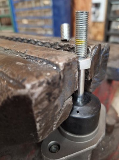
Before removing the m/c, I marked the pushrod where the shaft ended (with the jam nut spun down out of the way). I removed the shaft from the pedal, unscrewed the shaft, then reattached the shaft to the pedal, letting it hang down. Pushing the pedal down to brake pedal height while holding the shaft next to the pushrod, I made another mark on the pushrod. The length between the two marks was how much had to be cut off the top of the pushrod.

Holding the m/c secure with the jam nut, off came the top. The yellow mark is the original depth of the shaft, the other mark is hidden by the jam nut.
20231105_123121.jpg
20231105_124056.jpg

I forgot to take pictures of the new pedal placement, more to come later.
 
Last edited:
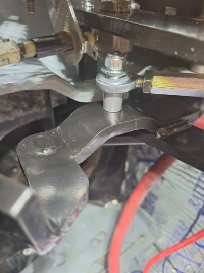
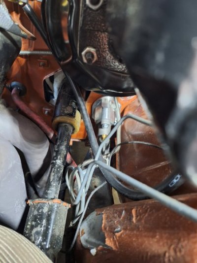
While I was under the dash, the next issue that needed attention was moving the brake switch terminal. SST even mentions in their instructions that the brake switch might interfere with the pushrod/shaft. The switch itself is out of the way, but the one male terminal points straight down at 6:00 and the female terminal collides with the shaft's shoulder bolt.
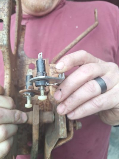
Greg pulled one of his B Body brake cages from his stash, and the brake switch terminal was in the same place so it's probably endemic to all B Bodies. No big deal, I removed the switch and clocked the plunger to 4:00.
Looking from the bottom up, the brake switch terminal and shaft head collide.
20231105_144753.jpg
Here you can see the original orientation of the switch terminal on Greg's brake cage, and the re-clocking on the Coronet's.
20231105_151246.jpg20231105_151308.jpg
Last piece of business under the dash was fashioning a pedal stop. The OEM style pedal stop that pops into the brake cage is just a thin piece of rubber and doesn't do anything. In my case, at rest, the pedal stop lever on the clutch pedal was 2" from the the upper rubber pedal stop. Greg found a rubber bump stop from one of his A bodies, and it was too short. He found one from a truck that was long enough, actually a bit too long. I measured the distance and Greg cut the piece at the line, and of course I measured wrong and it was now too short. A thick washer closed the gap. It's imperative that the m/c pushrod be fully extended at rest; exerting pressure on the pushrod will move the throw out bearing forward, engaging with the pressure plate fingers and causing premature wear. The clutch pedal just barely touches the rubber stop at rest.
20231105_144544.jpg20231105_144600.jpg
 
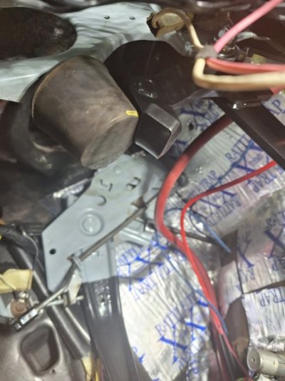
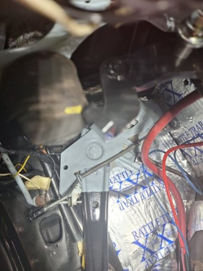
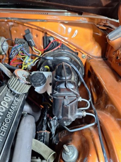
Moving onto the engine side of the firewall, with the m/c removed it clear to see that the shifter tang is in the way.
20231105_125029.jpg
Nothing a reciprocating saw can't fix.
20231105_131131.jpgIMG_20231106_183233.jpg
 
I might be motivated to make a call to SST and enlighten them on the discrepancies that are found when installing these transmission kits.
One is the trans tunnel cutout template. Imagine how pissed you might be if you cut a 10" x 13" hole in the car when a 4" x 6" hole is adequate?
They included the template needed for the TKO series, a transmission they don't sell anymore.
Second is the clutch pedal. Here now is two cars I've worked on where both had this lever in the wrong spot:

SST 85_LI.jpg


This makes it so that at rest, the pedal could sit up at least 1 1/2" higher than the brake pedal, maybe even more. This requires the addition of some type of extended bumpstop which may not be easily found by others. It is a simple fix....weld the bracket in the right spot and it will fit like stock.

Third, they should bore the bell housing a couple thousandths over the size that they are. The interference fit is a pain in the *** and causes anger and anxiety over what may be wrong.
 
Last piece of business under the dash was fashioning a pedal stop. The OEM style pedal stop that pops into the brake cage is just a thin piece of rubber and doesn't do anything. In my case, at rest, the pedal stop lever on the clutch pedal was 2" from the the upper rubber pedal stop.
Today I talked to Chris at SST tech support. I don't know if he's their only tech or its coincidence, but he's the one I talk to every time I call. I explained what's going on with the clutch pedal and in his words a clutch pedal stop is unnecessary with the hyd clutch setup. The exception would be road racing or drag racing where the driver is constantly side-stepping the clutch pedal. Even then, he made it clear that the m/c pushrod should be fully extended at rest.
In my case, the rubber stop is already installed and adjusted so that the clutch lever barely touches at rest so I'll leave it as-is.
 
This is from a video that I just watched:
1699601639435.png


The red lines signify the profile of the TKX.
 
Great write up! Sorry I'm a few days late and catching up. A couple of things:
1) Transmission installation: When I had my 23 spline A-833 it slid in and out like butter - I really could remove and replace it in less then 2 hours, by myself. I never had an issue. But my Passon A-855 overdrive has an 18 spline input shaft. That has been a royal pain in the butt to get seated in the bellhousing. In all three cases when I have installed it, the engine has been out of the car. I can't imagine trying to get it installed with the engine in the car! In installing mine, I put the transmission in gear and rotated it slightly to try and get the input shaft aligned with the clutch. But it still took all the stars to be aligned before it suddenly slipped into place. What a pain!

2) Clutch and brake pedal height: My car is a factory 4 speed, but I changed my brakes to power brakes. After all was installed, my brake and pedal height was different. In case it is helpful, below is my thread on making both sit at the same height.
Brake Pedal Height Issues

I'm sure you're going to love driving the TKX! :thumbsup:
 
2) Clutch and brake pedal height: My car is a factory 4 speed, but I changed my brakes to power brakes. After all was installed, my brake and pedal height was different. In case it is helpful, below is my thread on making both sit at the same height.
Brake Pedal Height Issues
Hawk, I think Greg did the same fix as you on his Charger, lengthening the dog bone to raise the pedal. On the Coronet, years ago I swapped from power drum/drum to power disc/drum and the braking works great so I didn't want to mess with success. Fortunately, the clutch m/c pushrod was long enough to cut down and lower the clutch pedal. I may be in the minority here, but I like the clutch pedal slightly higher than the brake pedal.
 
Everyone was busy Saturday so we resumed the festivities on Sunday. Dwayne (68 Sport Satellite) drove up from the Bay Area to hang out with the boys.
20231112_153015.jpg20231112_153027.jpg
Left to my own devices, I got to crack-a-lacken on the Coronet. Two things that I quickly crossed off the list was installing the driveshaft and filling up the trans with ATF fluid. SST sends two kinds of fluid - "cheaper" Dextron for the initial 500 mile break in, and Valvoline synchromesh for the long haul.
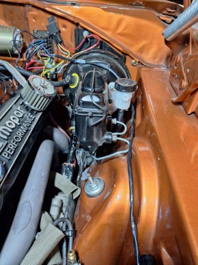
Next was mounting the reservoir and installing the high and low pressure lines. The reservoir comes with a bracket that gives two mounting options: directly to the firewall or inner fender, or to the brake m/c. There is no room on the firewall or fender so the m/c it is.
Not much room down there.
20231112_111125.jpg20231112_111108.jpg
The bracket allows the reservoir to be mounted on either side of the m/c. I mocked up both sides to see which side I liked best.
20231112_111100.jpg20231112_111436.jpg
The engine side was too close to the breather and would've been in the way if the valve cover needed removing, so the fender side it is. The fender side is less forgiving if the reservoir ever leaks the DOT 4 brake fluid. But you can see below the m/c that I've already experienced a leak from the m/c lines, damaging the paint on the shock tower.
The low pressure rubber hose is cut-to-fit; I ran the hose underneath the brake m/c and it tucked nicely around the back of the shock tower.

20231112_143435.jpg
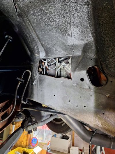
The best way to install the hose to the m/c is through the sight hole in the fender.
20231112_115905.jpg20231112_115934.jpg
Another thing to remember: tighten the low pressure nipple before installing the m/c. The orientation in the picture is the best angle pointing down, but I hadn't tightened it. Thank goodness for the sight hole as I was able to tighten the jam nut with an open end wrench.
 
Last edited:
Next up was the high pressure line. Here was another example of me creating additional work and burning daylight by not following the installation instructions. There are multiple tasks during the assembly that can be completed out of order to the instructions. For instance, the instructions had the installer fill up the tranny with fluid prior to installing it in the bell. I chose to wait until after the trans was installed because I figured it was that much less weight sloshing around as we were wrestling to slide it in. I have a transfer pump so delaying the fill up was inconsequential.
The instructions wanted the hyd line installed in the concentric slave cylinder (CSC) while the BH was still off the engine. With the BH on the bench the entire front end was open, allowing the hyd line to be aligned and tightened down with no obstructions. The BH is then installed to the engine with the CSC resting inside the register hole. When installing the trans, the input shaft goes through the CSC and it self-aligns with the shaft. Last week we installed the trans with CSC already on the input shaft, but of course without the hyd line attached.
Although I zigged when I should have zagged, in the end the trans and hyd line is in. But yesterday it took Dwayne's hands and nimble fingers to start the line in the CSC.
This pic from last week shows the CSC in place. The small circular red cover protecting the CSC threads is visible.
IMG_20231106_183242.jpg
The hyd line is in. Thanks Dwayne!
20231112_143646.jpg
With the cover in place, but not yet secured.
20231112_143604.jpg
The m/c side of the hyd line was just as challenging, but not from a lack of reading comprehension. There's just no room to maneuver to align the threads to the m/c. My hands have the manual dexterity of a hippo so I was getting nowhere fast. The day ended and I resolved to tackle the line next week. Well, after Dwayne and I left, Greg gave it a shot and he had the line in and tightened down before I made it home. Thanks Greg! It takes a village...
 
Toward the end of my framing career, I got a reputation in the company for being THE guy to send to do the weird "fixes". I was tasked with tearouts and rebuilds of stuff, repairs of damage and other things while doing it fast and as cheap as possible. Problem solving skills was a huge asset there.
The pressure line fitting was done with the index fingers on each hand opposing each other to press down and turn at the same time. My left arm between the firewall and header, my right hand sticking through the opening in the fender apron for the rear alignment cam.
Looking back, It looks like I did put the bearing on the bell during my swap...

SST 454.JPG


Sorry that I didn't remember that. It could have saved you some trouble.

It looks like if no huge surprises come along, the project is approaching the 4th quarter.
What remains to be done?

The clutch master cylinder needs to be bled, the starter needs to be bolted in and wired, shifter boot needs to be mounted then the interior can be put back together.

The TKX does fit cleaner with less tunnel surgery but it still requires some work to finish out.

IMG_4288.JPG


The boot has a base ring with 8 holes. The trim ring has 4.

IMG_4294.JPG

The 12, 3, 6 and 9 o'clock holes do match the base but the base has the other 4 at approx 10:30, 1:30, 4:30 and 7:30. I suppose that they have those to first secure the base and boot, then use the chrome ring to lay over the carpet to finish it off.

You can't just attach the boot to the existing trans tunnel though. The tunnel is too close to the trans case:

IMG_E4282.JPG


IMG_E4292.JPG


Because of this, you need a bit of a standoff to raise up off of the trans tunnel, a small base tower so-to-speak. This will allow the mounting screws to secure the boot and trim ring while clearing the trans case.

IMG_4301.JPG


A simple cardboard pattern was made to see what works. The goal is to make it as low as possible to look cleaner and to allow the RE-use of the original carpet.

IMG_4302.JPG


SST provides a simple sheet metal plate with a rectangle hole cut in it.

SST 290-1.JPG


The TKO needs the sheet that big. The TKX will not. It will be cut down to fit.
 
Here’s a picture from someone on another forum. They’re installing a Tremec manual in place of an automatic. I didn’t get if it was a five speed or six speed. Can you tell by the picture? He did very little cutting to get it in.

IMG_5472.jpeg
 
Last edited:
The trans tunnel looks different from the 66-70 B body tunnel. Note how it is squared off behind the console brackets...That isn't familiar.

That shifter tower is round. The TKO and TKX 5 speeds have a rectangular tower.

IMG_4283.JPG


I doubt that is a 6 speed Tremec either. Those are so tall, I'm told the trans tunnel gets cut a lot more than it does with the TKO.
Maybe that is someone's own project using a trans sitting lower than SST and American Powertrain kits. That would surely put the drive line at a weird angle.
 
Sorry that I didn't remember that. It could have saved you some trouble.
No apologies needed. This is my project. Besides, not only did I read the directions, I highlighted the text about installing the hyd line first, and made notes in the margins.
 
It looks like if no huge surprises come along, the project is approaching the 4th quarter.
What remains to be done?

The clutch master cylinder needs to be bled, the starter needs to be bolted in and wired, shifter boot needs to be mounted then the interior can be put back together.
A few additional things: install the speedo cable and reverse light harness; reassemble the fan and shroud assembly, install the side and bottom BH covers, hook up the exhaust. The kit comes with a support bracket for the high pressure hyd line, but its optional. It can be attached to one of the threaded holes in side of the BH or to the firewall. I'll have to see.
Shifter boot will take the longest.
The TKX does fit cleaner with less tunnel surgery but it still requires some work to finish out.

View attachment 1556845

The boot has a base ring with 8 holes. The trim ring has 4.
Looks like Tremec supplies the same trim ring to all their kits. The 15 year old Keisler Engineering 5 spd in the Dart has the same trim ring.
View attachment 1556846
The 12, 3, 6 and 9 o'clock holes do match the base but the base has the other 4 at approx 10:30, 1:30, 4:30 and 7:30. I suppose that they have those to first secure the base and boot, then use the chrome ring to lay over the carpet to finish it off.

You can't just attach the boot to the existing trans tunnel though. The tunnel is too close to the trans case:

View attachment 1556847

View attachment 1556848

Because of this, you need a bit of a standoff to raise up off of the trans tunnel, a small base tower so-to-speak. This will allow the mounting screws to secure the boot and trim ring while clearing the trans case.

View attachment 1556849

A simple cardboard pattern was made to see what works. The goal is to make it as low as possible to look cleaner and to allow the RE-use of the original carpet.
Greg fashioned the cardboard pattern last week. Looks perfect.
View attachment 1556850

SST provides a simple sheet metal plate with a rectangle hole cut in it.

View attachment 1556851

The TKO needs the sheet that big. The TKX will not. It will be cut down to fit.
Then spot welded and seam sealed. Greg's the welder.
Could we be finished this weekend?????
 
Last edited:
The pressure line fitting was done with the index fingers on each hand opposing each other to press down and turn at the same time. My left arm between the firewall and header, my right hand sticking through the opening in the fender apron for the rear alignment cam.
I could not get my arms up enough to start the threads. While Greg and Dwayne were working on the Satellite, I was raising and lowering the Coronet trying to find the sweet spot where I could start threading. I must've raised the lowered the lift 3 or 4 times. I was waiting for one of them to come over and ask WTF I was doing.
 
As the project winds down I want circle back to the BH side cover. The side cover has a spongy gasket that hangs loose and is secured as the cover is tightened down from the inside of the bell, compressing the gasket. Greg told me a couple of weeks ago what a PITA it was to simultaneously hold the gasket in place while tightening down the cover.
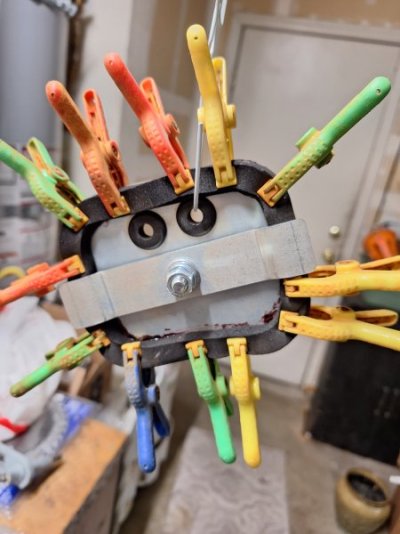
I glued the gasket with some high tack gasket sealer, held in place by micro-clamps. (Never seen clamps this small before; Greg had a stash that I borrowed. Turns out HF sells them).
20231021_194641.jpg20231021_195234.jpg
Makes a difference when installing the cover
20231112_143604.jpg
 
i use those harbor freight clips to hang my Christmas lights around the house.

nice progress on the project

we’ll need you to create a YouTube channel and post some vids :p


watermelon
 
@CoronetDarter with the install of the TKX, how much longer is the new driveshaft compared to your old one with the automatic?
@Kern Dog with the install of the TKO, how much longer is the new driveshaft compared to your old one that you removed?

What diameter did you guys go with?
 
Auto Transport Service
Back
Top