• When you click on links to various merchants on this site and make a purchase, this can result in this site earning a commission. Affiliate programs and affiliations include, but are not limited to, the eBay Partner Network.

Tremec TKX 5-Speed Conversion

Since I’ve never worked in a repair shop, I can only guess that they’d need spare stalls so the mechanics can alternate between projects to maximize profits.
A job like this would most likely be time and materials. If the shop quoted a set amount, they most likely will shoot themselves in the foot due to surprises.
 
Rich and Greg, Glad to see that ingenuity and persistence got the bellhousing job done. I'm enjoying following your adventure. Thanks for taking the time to post it. It's a great roadmap for those thinking of following in your footsteps...
Thanks Dave. The common thread here (pun intended) is documenting the trials and tribulations of taking on a project like this. I can't count how much information I gleaned over the years searching through this site.
 
Got through Halloween relatively unscathed. In our house we wait until the last minute so Monday and Tuesday were spent running around getting supplies and candy. Wednesday morning I spent two hours getting my costume together. Then last night going trick-or-treating with the grandkids and then passing out candy the rest of the night. They must bus the kids into our neighborhood because we get over 100 kids ringing our doorbell every year.
I'm the one with the hat.
20231031_200412.jpg
 
Knocked out a few things this weekend. Also took two steps forward and will be taking one step back this coming weekend.
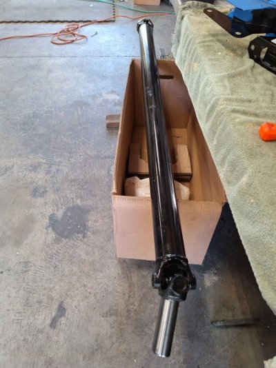
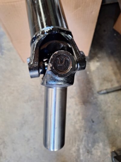
Picked up the driveshaft last week from Driveline Specialties in West Sac. I've used them several times over the years and they do good work with quick turn around times. They charged $500, the same as SST would, but no shipping and I brought in the original driveshaft for them to see. The pinion U joints are 1330's and I know they're common and SST has them in stock. But I feel better bringing the 'shaft in, they measure the cups just to be sure. For now we stored it up in the rafters until its time to install the tranny for the last time.
20231028_105442.jpg 20231028_105458 - Copy.jpg
 
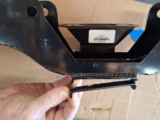
Cut off the offending flange from the crossmember and painted it gloss black. It also was set aside until the final tranny install.
Greg is the hand model.
20231028_145216.jpg
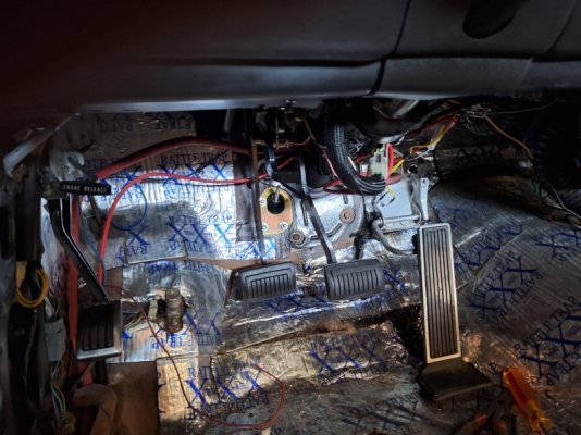
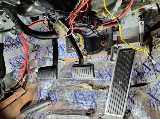
Next up was installing the clutch master cylinder to the firewall and hooking up the linkage to the clutch pedal.
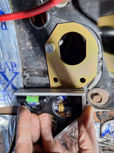
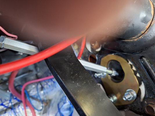
Use the interior-side mounting plate as a template to mark the 3 holes. I held a level at the bottom before marking to ensure the m/c would be level. The fitment is really tight, you can see how close the right edge of the plate sits next to the steering column mounting bracket. The bolt actually starts on the engine side of the firewall, this one is in backwards just to hold the plate for the picture.
20231028_130625 - Copy.jpg
I didn't take any engine side photos during the install, which is just as well because the m/c has to come out. More on that later.
It's another tight fit on the engine side navigating between the brake m/c and steering column. To further complicate things, the car was a column shift automatic and the linkage bracket on the steering column fights for real estate with the m/c. There's room for the m/c to attach to the firewall, but it's going to interfere with the high-pressure line going out to the slave cylinder in the bellhousing. Those of you who read Greg's TKO install thread may remember he had the same issue with his 70 Charger's ignition lock bracket. After we remove the m/c, I'll wind up cutting off the bracket like he did. I'll take pics this weekend.
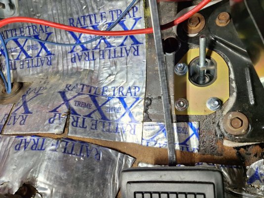
Here's the view of the m/c installed from the interior viewpoint. The threaded pushrod from the m/c screws into the linkage sleeve and secures with the jam nut. The hole in the upper left is for the speedo cable.
20231029_114005.jpg

20231028_145243.jpg
 
You mean THIS lever??

SST 107.JPG

That oval hole behind it is where the clutch linkage passes through to the clutch master cylinder.

SST 128.JPG


Here you can see how the two seem to share space quite close to each other.
 
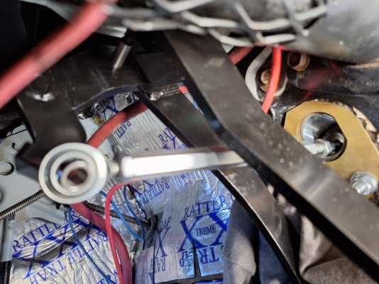
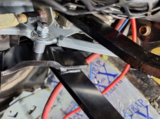
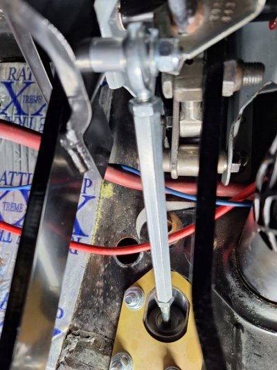
The sleeve threads onto the m/c pushrod and attaches to the clutch pedal with a shoulder bolt. It's imperative that the pushrod and sleeve are in a straight line when connected to the pedal. If they're cocked to one side, the piston inside the m/c will wear unevenly in the bore and eventually create a leak. When this happens you have no clutch.
The kit comes with a spacer, and in my case it needed the spacer between the pedal and sleeve head. The sleeve attaches to the pedal with a bolt and lock nut.
20231029_121336 - Copy.jpg 20231029_123906 - Copy.jpg 20231029_123935 - Copy.jpg
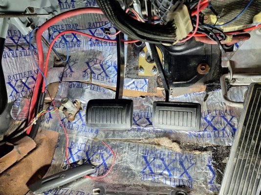
The problem is that the clutch pedal sits at least an inch higher than the brake pedal. I'm not OCD enough to require them to be perfectly even, but the clutch pedal needs to get close.
20231029_124122 - Copy.jpg 20231029_124132 - Copy.jpg

However, the female threaded bore in the sleeve is shorter than the male threaded pushrod so it bottoms out, not allowing the pedal to be adjusted downward.
In this picture you can see how there's at least ten threads left on the pushrod after the sleeve bottoms out.
20231029_121152 - Copy.jpg
Here's another example of the advantages of working on a project with someone else. I just want to get the tranny installed and get the car back on the road, so I told Greg I'm going to leave it as-is for now and go back to it over the winter and fix it in my garage. But it's really helpful to have a dispassionate friend weigh-in with alternative, sound advice. And not dispassionate in that he doesn't care, because he does, but in the sense that it's not his car so he can look at this obstacle more objectively. In the end I'm taking Greg's advice and pulling the m/c this weekend. But first, I'll mark the threads as they are, then unbolt the sleeve from the pedal and unscrew it from the pushrod, then reattach the sleeve to the pedal. As Greg depresses the clutch pedal level to the brake pedal, I will mark the end of the now free-floating sleeve on the pushrod threads. The difference between the two marks is how much the pushrod has to be shortened.

20231029_121347 - Copy.jpg
 
I figured that while the car is apart, it makes sense to do the stuff that is harder to access later. It is only a small detour but will save time overall.
This is par for the course with big projects like this. I've heard some call it mission creep but I call it the snowball effect, referring how a snowball increases in size as it rolls down the hill.
The whole concept of fixing stuff along the way since I'm already here makes sense in General terms.
We often start a project with the intention of just working straight through with no distractions.
THEN we encounter a myriad of obstacles and have to find solutions for them.
I used to encounter those things and bitch about them.
Sometimes though....they give you a chance to flex your mental muscles and use creative thinking to devise a workaround.
 
Maybe check the SST book on the clutch. I think the clutch needs to hit the stop plate when it is fully out(just a hair of slack. This makes the clutch pedal height what it is. You would need to chase the brake pedal and I do not remember if that can be adjusted or not. If you adjust the clutch pedal down and it will not rest on the stop then the piston in the slave cylinder would go to full retraction and hammer the housing. My gut tells me that will kill it quickly.
Now, if you are going to shim the pedal stop down to follow the pedal move then ignore everything above.
You're right, you covered it in post #41. So the pedal adjustment is made after the trans, hyd t/o bearing, and hyd lines have been installed and bled.
 
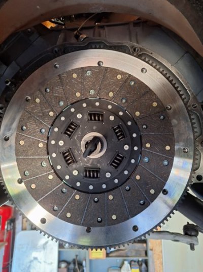
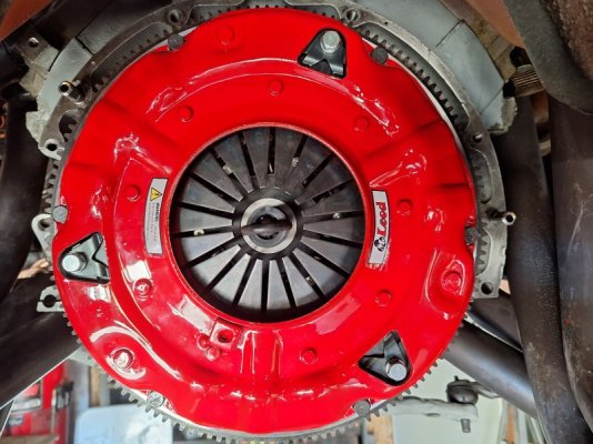
The clutch and pressure plate are installed. Instructions say to torque to OEM specs; 30 ft/lbs using blue LockTite.
20231029_140748.jpg 20231029_151309.jpg
The McLeod clutch alignment dowel is for an OEM Chrysler 4-speed and will not fit the TKX. SST provides a separate alignment dowel specific to the TKX.
 
Did a little house cleaning while under the car.
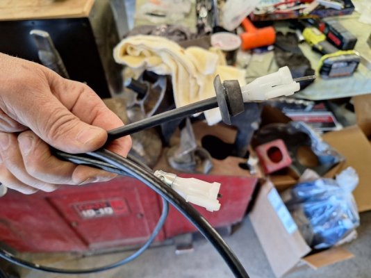
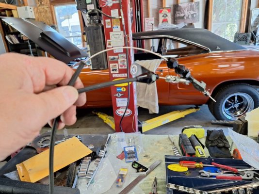
Removed the speedo cable. Ironically its a brand new cable, installed in the 727 and ran through the firewall but never hooked up to the speedo. The original cable laid on one of the header tubes and the sheathing welded itself to the metal speedo cable, preventing it from spinning. The sudden torque broke the speedo gears. By the time I got the speedo repaired and reinstalled in the car, I had decided on the TKX swap so there was no sense hooking it up.
New repro speedo cables come with the firewall grommet attached to the cable, otherwise the grommet can't be slipped over the cable ends. The SST cable didn't come with said grommet, so I had to cut a slit to transfer it.
20231029_130210.jpg

I also detached the Lokar kickdown cable from the carb.
20231029_132044.jpg
 
Instructions say to torque to OEM specs; 30 ft/lbs using blue LockTite.
Lately I've been using "orange" for stuff that I really want to stay in place. It's removable and stronger than blue (they say 3x).
I'm not suggesting you change (the blue is fine and per instructions), but just posting here for everyone FYI. :thumbsup:

20231104_082459.jpg
 
Lately I've been using "orange" for stuff that I really want to stay in place. It's removable and stronger than blue (they say 3x).
I'm not suggesting you change (the blue is fine and per instructions), but just posting here for everyone FYI. :thumbsup:
That's good to know. I used red on the flywheel bolts and switched to blue on the pressure plate.
 
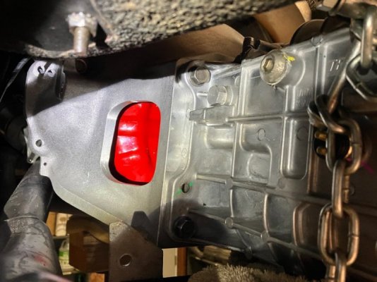
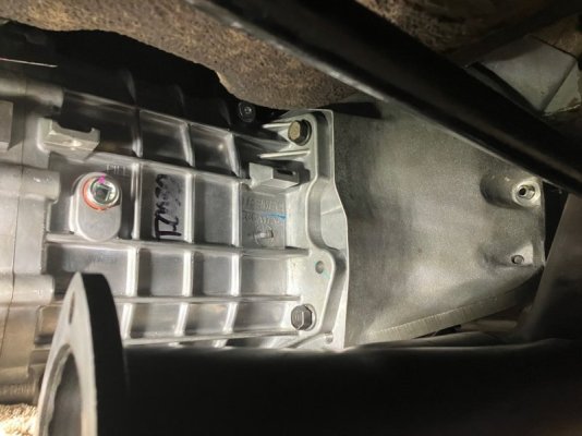
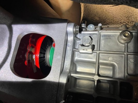
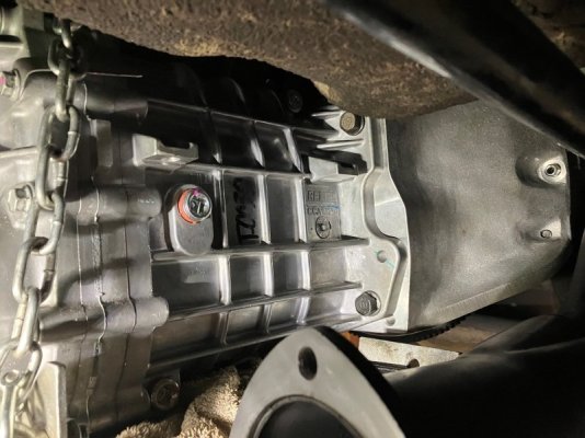
We spent most of the day in the garage and got a lot accomplished, and I'll backfill the details. But first I'll cut to the chase: the TKX is in! It took a lot of finagling over about a two hour period to wrestle it home. With the tapered spline shaft its less forgiving than the old 833's.
We had the tranny in once before (without the clutch disc and pressure plate) to measure the driveshaft, so we knew we had the space to mate it to the BH face. Before rolling the trans under the car, Greg smeared some of his assembly lube on the spline shaft and the outside of the slave cylinder collar to help glide it in. The initial jockeying of the trans jack was fairly repetitive; it was a series of raising and tilting the jack while rolling it backwards to get the tail shaft to clear the H pipe. Once the H pipe was cleared we could roll the jack back enough for the spline shaft to clear the BH, and at that point we rolled the jack forward and was able to push the tranny in all the way to the slave cylinder collar. The bullnose of the spline shaft was past the clutch disc and into the pilot bearing, although it was impossible to see or gauge how far.
We got the trans to within a 1/2" of the BH before running out of steam. No matter how much we pushed and twisted the trans it wouldn't go in any further.
After struggling for about an hour, we decided it was time to ignore the SST instructions and use the power of torque to pull the tranny in. Greg had extra long GH bolts that we ran through the tranny mount holes and engaged the BH, tightening until we felt resistance. Then with Greg and I on opposite sides of the tranny, we methodically in a cross-bolt pattern, started drawing the trans to the BH one bolt at a time. It didn't take long before the trans mated to the BH. Full disclosure, the SST instructions warn in BOLD, ALL CAPS TYPE, not to do this for risk of breaking off a ear.
IMG_20231106_183235.jpgIMG_20231106_183237.jpg
IMG_20231106_183240.jpgIMG_20231106_183242.jpg
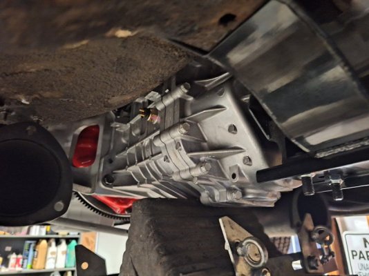
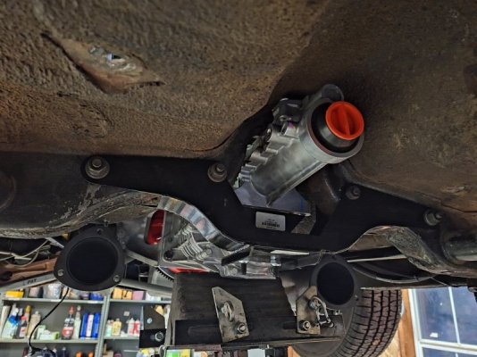
We had to use a rubber chock on the jack to gain enough height to line up the tranny to the BH and gain enough room to slip in the cross member.
20231105_171107.jpg
Raising the tail shaft, we were able to start one of the outside bolts. The tranny still requires some jockeying and twisting to line up the other three bolts.
20231105_171051.jpg
 
Auto Transport Service
Back
Top