• When you click on links to various merchants on this site and make a purchase, this can result in this site earning a commission. Affiliate programs and affiliations include, but are not limited to, the eBay Partner Network.

'64 Fury Pro-Touring

So after all the work with hinges I've thrown in the towel and decided to go with 4 pins and no hinges; I just don't like how they were working. Oh well, it's all a process and this was just part of it.

I put the engine/trans back in so I could mark the cut-outs in the hood. You can see, by how high the carbs sit compared to the cowl height, how low the body sits over the chassis. I always knew this was going to be the case but figured the '65 Hemi scoop would be tall enough to cover, but it's not looking like it. I believe VFN makes a tall version of the Max Wedge scoop, and maybe the '65 scoop, so I'll be looking into that.

:thumbsup:WOW....Crossram Hemi Badazz
 
Whooops, not so fast there M-nation, that bad boy is a wedge with a cross ram; think Max Wedge.
Regardlwss, thanks for reading the blog, I appreciate the enthusiasm.
That's even better in .my books....I have to blame my phone for the small picture lol
 
Had some pretty major surgery at the end of June then went on a 3-week business trip so the Fury has been sitting with no progress for a couple months but I'm back at it again!

Gave up on using the factory springs; even in their modified form I just wasn't happy with their functionality and decided to go with a A-12 type of pin-on hood arrangement, so here's some pix of what I came up with:

These are the mounts I fabbed up from 1" x 2" rectangular tubing. I had to narrow them to 1 1/2" so there was a bit more work than I figured on, but overall an easy fab job.
IMG_1520.JPG

IMG_1521.JPG

Then I ran a string line from the cowl to the rad support, making sure the string line was equally distanced (front to rear and side to side) on each side and burned in the mounts. You can see the bare spots on the front cage tube where I cut off the forward hinge mount.

IMG_1522.JPG


IMG_1523.JPG

In the pictures above you can also see the hinge supports on the cowl, which I decided to remove. I drilled out the spot welds hoping I could then do a little metal finishing to bring the cowl back into shape, but as usual the spot welds cursed me and the sheet metal on the cowl tore as I tried to remove the braces. More patch work followed on both sides, though I only took a picture of one. I'll post some pix of the finished work when I get back into the shop.

IMG_1410.JPG
 
Had some pretty major surgery at the end of June then went on a 3-week business trip so the Fury has been sitting with no progress for a couple months but I'm back at it again!

Gave up on using the factory springs; even in their modified form I just wasn't happy with their functionality and decided to go with a A-12 type of pin-on hood arrangement, so here's some pix of what I came up with:

These are the mounts I fabbed up from 1" x 2" rectangular tubing. I had to narrow them to 1 1/2" so there was a bit more work than I figured on, but overall an easy fab job.
Then I ran a string line from the cowl to the rad support, making sure the string line was equally distanced (front to rear and side to side) on each side and burned in the mounts. You can see the bare spots on the front cage tube where I cut off the forward hinge mount.

In the pictures above you can also see the hinge supports on the cowl, which I decided to remove. I drilled out the spot welds hoping I could then do a little metal finishing to bring the cowl back into shape, but as usual the spot welds cursed me and the sheet metal on the cowl tore as I tried to remove the braces. More patch work followed on both sides, though I only took a picture of one. I'll post some pix of the finished work when I get back into the shop.

Bob, it's good to see progress. I sold my car a few months back. Take care, Roger
 
Glad to see you back in action!
 
Thanks 7, it's been a bitch of a summer but I'm back on it.
How's that stunning Charger, anything good going on lately?
Just driving it:thumbsup:. Been busy building my garage, kids sports and the honey do list.
 
Hey Bob, you mind if I stop by again when I'm in town for SEMA?
 
Roger, when it gets closer I'll touch bases with you. Especially since you say you moved to a different shop. I'm coming in monday afternoon and leaving thursday when I'm done.
 
Roger, when it gets closer I'll touch bases with you. Especially since you say you moved to a different shop. I'm coming in monday afternoon and leaving thursday when I'm done.
Shop is in the same complex, just a few doors down. Chose to rent space from a friend as opposed to having a shop of my own, it saves me a TON of insurance $$'s but comes with the expected mess, etc.

See ya soon
 
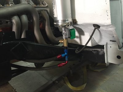
Got a bit of time to work on the Fury this weekend so I decided to mount the Moroso Accumulator, work out the plumbing for it, as well as begin mocking up the serpentine belt and pulleys, so here a a couple pictures showing what I was up to.

I was throwing different ideas around about where to mount the accumulator and no place made more sense than the firewall. I don't have power brakes so there isn't any space issues and the steering column is inboard of the accumulator by about 4", so it made sense to mount it here. It's a fairly short distance to the oil line that runs between the pickup and the "In" side of the pump, I'll just have to clear the header tubes.
One important thing to note is the manual valve on the bottom of the accumulator; this will be changed out for an electronic pressure valve (ordered today) for hassle free use as a pre-primer as well as a measure of safety against low oil pressure.
IMG_1528[1].JPG

This picture shows the relationship between the oil pump and filter mount, which will be easy enough to plumb. I'm going to use a 180* fitting on the inner port of the filter mount, which will run to the top (out) port of the pump, and a 90* fitting (as shown) on the outer port of the filter mount, which runs to the bottom (in) port of the pump.
IMG_1529[1].JPG

I've got heated seats for the Fury (Caddy CTS-V seats, shown earlier in the build) but living in Vegas means I really do want A/C,, and while there are some serpentine belt systems out there I can do this on my own without spending a fortune. How?
Use an off-the-shelf mini alternator (120+amp) mounted on stock Mopar mounts, a factory replacement power steering pump mounted on factory mounts, a Sanden A/C compressor mounted on a custom bracket, an idler pulley (metal, not plastic) off something late model, and serpentine pulleys from 440Source.
The image below shows a quick mock-up of an ND (Nippondenso) mini alternator mounted using the stock Mopar mounts. It fits great though I'll have to do some adjusting fore/aft to get the pullets to line up correctly, but I'll wait until I get the pulleys from 440Source before I start making any adjustments. One advantage of this setup is the fact the alternator will be used to tension the belt so I don't have to worry about mounting a belt tensioner, just an idler.
Another advantage of this setup is the amount of space I have below the alternator to mount the A/C compressor; there is SO MUCH space I'll have absolutely no problem getting a modern compressor to fit, though I'll have to fab up a custom mount, but that will be no problem.
IMG_1530[2].JPG

Today I'm heading to the shop to clean up the alternator so we can get the model number and figure out what it came out of; I have my doubts it actually functions, and even if it does, I also doubt it puts out enough amperage to run everything I'll have in the car.
 
Took a few hours yesterday and got the Moroso Accusump plumbed (but not wired), so here are a few shots of the finished layout:

I know it's probably overkill but I've always preferred running dual filters so these shots show the dual filter setup along with the Milodon external oiling plate (blue anodized plate mounted to the oil pump). What worked out really nicely with the dual filter setup are the dual inlets and outlets, they allow for a much easier layout of the -10 lines.
I don't much care for the look of steel braided line so that's why I use the black braided nylon, which I think will go great with my accessory drive and hemi orange block. It's also MUCH easier to work with than braided steel.
01.jpg


04.jpg

Wow, now I wasn't expecting the electronic pressure valve and fittings to be nearly this long, but in the end they worked out OK; the lower line (with the 90 degree fitting) is level with the line/fitting for the oil supply going from the pan pick-up to the pump, which means they are both a couple of inches above the bottom surface of the frame, so they'll be plenty safe. BTW - Yeah, I know, the check valve isn't shown; I'll add it in after I receive it (next week some time).
Both braided lines run forward, passing over the lower a-frame (not installed), and with only 4" of shock travel there's no issue about the lines being pinched during compression of the suspension.
Later I'll be adding a couple of cushioned hose clamps to hold the lines tightly against the inner surface of the frame rail to ensure they stay away from the header tubes and/or any other possible damage.
03.jpg

in a previous post I mentioned a mini ND alternator I want to use, so I sent it out to a local shop to a) see if it's still functional, and if so, what kind of amperage does it produce, b) what model it is so I can get a replacement if necessary, and c) see if the shop can up the output to 120+ amps. I'm waiting to hear from them so I'll keep you posted.
My next bit of fabbing will be for the A/C pump mount. I haven't even looked at the block to see what mounting lugs are present, but honestly, I'm not worried, I'll get it figured out. 02.jpg
 
Last edited:
Heres how it all lined up with the bracket tacked. It's tough to see all the different suraces and how the line up, but it's MUCH better than when I started.


Next came the kitty hair on the outside of the fender. The kitty hair squeezes into the gap, filling it while adding strength without the bulk of resin and glass cloth. This work was all done with the fender mounted so as to hold its shape.
When the kitty hair dried I pulled the fender and turned to the resin/cloth to the inside surface. This will add lots of strength the kitty hair doesn't have. In this shot, taken just before the resin/cloth was added, you can see the kitty hair has filled most of the gap, though not all.
Here's a shot after the resin/cloth was added.
Tomorrow I'll get everything smoothe out and get back to aligning the fender with the door and finalizing the gaps.

You are one very determined fellow Bob. Good to see the progress you've made. But my goodness the amount of work that new fiberglass needs is something else.
IMG_4438.JPG
 
Finally, after what seems like months away from the Fury I got back to work this week and the progress, while visually minimal, has taken a great step forward, and hopefully I'll get some momentum going and the car will progress somewhat quickly from here (where's the "fingers crossed smiley face?).

Unsure whether some of my sketchy welding results were my lack of experience, poor technique, or a combination of these, I twisted Jimmy's arm and convinced him to make the trek over to my shop for the day to give me a hand and the results were outstanding. Along with getting a number of vital pieces finish welded into the chassis Jimmy was kind enough to give me some pointers and instruction in welding that should really help me in the future.

The engine mounts, noted in an earlier post, were sent off to Jimmy's shop to be finish welded (TIG), so he brought those back with him and once mounted on the engine we dropped the engine back in place, tightened everything up, ensured we had between 2.5 and 3.0 degrees of tail down angle, and Jimmy proceeded to finish weld in the frame tabs for the mounts.

Here's the drivers side and the picture below that is the passenger side:

View attachment 454255

View attachment 454256

Once we got the engine mounts completed we moved on to the Truck Arm Cross-member, which I had previously tacked in place. Jimmy and I discussed the various options in terms of the vertical placement (the fore-aft had already been decided by the wheelbase) and in the end we decided to place the cross-member as far towards the top of the frame rails as could be managed without interfering with the floor, which is going to sit directly on top of the rails as opposed to channeling the floor over/around the rails.

This is the Truck Arm Cross-Member finish welded in place and the picture below details the welds:

View attachment 454257

View attachment 454258

With the engine and suspension placement now finalized Jimmy and I sat back and began to plan out our next move, which will be the firewall and floor placement, but this brought about another set of issues (what else?), such as exhaust placement and interference between the firewall and engine. Knowing these two areas had to be addressed here's what we decided:

Exhaust - as noted in an earlier post we will be using V-band clamps on the exhaust, both eliminating the need for gaskets as well as allowing for 360 degree rotation of tubing, but we've now decided to use the V-bands even more extensively as well as something a bit more out of the norm: instead of cutting oblong holes in the frame rails and lining the inside of this passage with sheet (forming a tunnel) and passing the exhaust tubing through the newly created tunnels we are going to weld the 3" stainless tubing directly into the frame rails, then run stainless tubing from the headers to the newly created frame/tube junction, joining them with V-bands, then running more 3" stainless on the outboard side of the rails, into 12" - 14" round mufflers, then blending into oval tubing that will exit out the sides of the car through openings in the rocker panel. I wish I had my desktop PC to work (killed it with a virus on Thursday) with because I'd draw up a quick picture in Photoshop to illustrate exactly what I mean. As soon as my PC is back up and running I'll throw something together.

What this solution offers us is tighter packaging as well as avoiding the chance of exhaust tubing touching the frame rails and rattling. We do realize the exhaust passing through the frame will cause a sensation all its own but I'm willing to take the trade-off. Besides, this method, combined with the use of the V-bands, will make maintenance of the exhaust system a breeze.

Next we moved on to the problem of interference between the engine, cowl, and firewall. With the engine set back we have (some 3" - 4" more than stock) we knew the firewall would need to come back, but how far we weren't sure, so we decided that rather than try and use the tattered and patched cowl we had in the car we would simply cut that entire piece out and patch in the one purchased from Texas Acres a month or so ago. This would also give us the advantage of having a couple of stock fender mount locations back on the car since the originals were lost to rust.

Jimmy and I carefully cut the excess material off the Texas Acres replacement cowl then outlined exactly what needed to be cut off the Fury. The replacement cowl went with Jimmy to be soda blasted and below is how the Fury looks with the cowl removed:


Luckily the window frame and the adjacent inner panels are all in good shape so melding the replacement cowl onto the body should be pretty straight forward as well as give us lots of strong material to work with. The one thing that's still up in the air is just how much we're going to have to pull the firewall back to clear the engine, and part of that question will be answered soon with the arrival of the A&A Transmissions Max Wedge Cross Ram.

This intake is a direct replica of the cross ram intake used on '64 Max Wedge cars and should work really well with the new Edelbrock Victor Max Wedge heads I've got. The one thing of concern is just how much of an overhang is there with the intake in place, hence the questions about firewall set back and clearance.

Here's a shot of the A&A Transmissions Max Wedge Cross Ram:

View attachment 454260

At this point I'm not sure what throttle body injectors I'm going to run, there are so many choices out there, but I am leaning towards dual Retrotek's since they have the appearance of carbs and they make a complete system that is set up for dual quads as well as being "self learning".

Here's the Retrotek throttle body:

View attachment 454261

That's it for now but it sure is nice to be back at it!

Love this pic. Pretty sure this is the first time in history that the motor weighs more than the car...

:thumbsup:

IMG_5980.JPG
 
Auto Transport Service
Back
Top