• When you click on links to various merchants on this site and make a purchase, this can result in this site earning a commission. Affiliate programs and affiliations include, but are not limited to, the eBay Partner Network.

'64 Fury Pro-Touring

Before my build goes any farther I want to throw a shout-out/apology to the guys at Sled City. A couple of posts ago I made a comment regarding the fit of my fenders so now it's time to take my foot out of my mouth. As I continue working on the front bodywork I found that when I welded in the core support it had moved, throwing the entire front end off. F'n dumbass I am!

My apologies to the guys at Sled City.

I have cut off the core support and am in the midst of rebuilding so I'll post some pix later.
 
Like I said in the previous post, I made the decision to cut off the entire rad support along with the fender supports and move it to the correct position. This meant cutting out the radiator mounts and moving them too, but that worked out for the better as well. Not really exciting pix but they do show the results.

And BTW - the first pic was one I forgot to post previously, showing how well I'd got the body lines of the fender to line up with the body line on the door.

IMG_1410.JPG

This is the finished product after two days of cutting and tacking; today (Sunday), I'll go back and finish weld everything.
IMG_1411.JPG

Another significant change I made was to move the mounting tabs for the fenders. On the previous layout I had the tabs mounted to the inside of the fender, so the bolts passed through the tabs and into the fender, but now the tabs are behind the fender, making for a much cleaner look.
IMG_1412.JPG
Same detail on the driver side.
IMG_1413.JPG

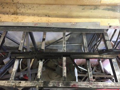
Looking from the firewall forward you can see the re-aligned rad support and where the fender braces mount to the support. Also note the removable cross-member in the rad support; with the Art Morrison chassis there's no way to load the engine from the bottom so making the top part of the rad support removable makes for a MUCH easier install.
IMG_1414.JPG

Knowing I had lots of final welding to do I pulled the fenders just before leaving the shop, so I thought I'd grab a picture that shows everything exposed. Oh yea, in the bottom right corner you can see one of the lower rad brackets. Nothing exciting but they're back in too.
IMG_1415.JPG
 
Took some time off for the holidays and to recover from surgery but I'm back at the Fury again.

I formed and installed the 1/2" aluminum fuel lines quite a while ago but to be honest, I never liked them. I was always concerned about them work hardening and holding up over the long run, so I bought a 50' coil of 1/2" stainless tubing and re-routed new fuel lines through the frame and along the inside face of the rocker panel. Below are a couple shots of the pass-throughs:

This picture shows the hole through the outside of the frame, just in front of the rear axle. The small bolt protruding from the floor pan (just in front of the frame hole) is the hold-down bolt for the fuel line bracket, which I'll show in an upcoming post along with the fuel lines and shielding.
IMG_1416.JPG

Below is a picture of the same hole, but taken from the inside of the frame rail. To keep the strength, rigidity, and integrity of the frame I formed 18 gauge steel patches and closed in the area between the holes. The picture above doesn't show this very well be the picture below shows it off really well. You want to talk about a lot of work making/installing the patches, but well worth it in the end.
IMG_1417.JPG

Below is a picture of the hole through the frame "outrigger". This is the part of the frame where the front of the leaf springs would normally mount, but with the truck-arm suspension the outrigger is used only for body mounting, so is under far less stress than in a normal, leaf spring application. To give myself room to work I made the hole much larger than necessary then welded in a patch (using the piece I'd cut out) bringing the hole down to finished size.
At the top center of the picture you can just see the 3" exhaust tubing, and this is where a muffler will be located, so keeping the fuel lines as far to the outside and away from the muffler was my primary concern. Both lines will covered by a shield I fabricated but still, the feed line will be placed down in the recessed area as far as possible while the return line is a bit more exposed. I'll show the lines and the shield in an upcoming post.
IMG_1418.JPG

The picture below shows the oblong hole in the center outrigger (there are 3 outriggers per side). This hole could be made MUCH smaller than the hole in the rear since the fuel line is pretty much straight at this point.
If you're wondering what the little square "box" is adjacent to the whole, it's the recessed area where the seats slide into. The seats have 2 hooks (one left, one right) at the front, and those hooks slide down into these recessed areas and capture a steel rod. Once in place there are two bolts (one left, one right) that bold down through the floor, holding the seats firmly in place.
One odd thing here: the factory CTS-V seats actually only have one bolt, and it's on the outer seat frame rail, but I didn't like that arrangement so I added a matching hold down on the inner seat frame. My theory is GM put the hold down on the side where the shoulder belt tension reel is, thus securing the seat and passenger, while leaving a bit of "give" by not attaching the seat to the floor on the side where the belt latches. Regardless, I didn't like it and added the second hold down.
IMG_1419.JPG
 
Once I got the fuel lines sorted I moved on to the sway bar mounts. I've been holding off as long as possible waiting for my friend Jimmy to fab up my new sway bar arms but, as usual, he's lagging way too far behind and I couldn't wait any longer so I took my original pair of arm and cut/welded them into the shape I want. I'll post pix of them shortly, but below shows how I made the adjustable sway bar mounts with 1 1/2" of fore-aft adjustment.

The car is inverted on the rotisserie so I leveled the chassis (left to right), took a long, straight tube and clamped it to the chassis, then used clamps to pull the lower A-arms so they are level (which they will be very close to at ride height). I then mocked up the entire sway bar/arm/links setup, adjusting the links so there is no pre-load on either one, then ensuring the links were perfectly vertical (measured in two places, 90 degrees from one another). With the links perfectly vertical this put the sway bar in its natural, unstressed position. Making sure not to move the bar, I moved the pillow-block/mount assemblies to they were centered on the frame rail and marked their positions. I then removed the sway bar assembly and cut out a section of the frame rail.
IMG_1420.JPG

Once the two sections of the frame were removed I cut out 2, 1 1/2" slots in each, then welded a 3/8" grade 8 nut to a 9/16" washer. The idea was to capture the nut inside a containment cell, thereby not allowing the nut to turn and the washer would a) allow the nut to slide fore and aft, and b) the washer would be keep the nut from falling out of place. If you look at the containment cell closely you'll see the sides are NOT even with the tabs at each end, the sides are raised leaving just enough area so the washer has room to fit (and slide unimpeded).
IMG_1421.JPG

I hope that explanation makes sense, but if not, the next couple pictures show exactly what the pieces look like assembled. The first shot shows the nut at one end of its travel while the second picture shows the nut at the opposite end of its travel.
Yes, the tab at the right end of the containment cell is overhanging the end of the plate; the tabs were all trimmed back substantially before welding in place.
IMG_1422.JPG


IMG_1423.JPG

Below is a finished plate with both containment/nut/washer combos in place (each pillow block uses two bolts to hold it in place):
IMG_1424.JPG

After fabbing up both plates it was time to weld them back into the frame. I used .035 wire on setting "E" (on my Lincoln 220 series welder) and without a doubt this is the best welding I've ever produced, the penetration was excellent, the feed speed was dialed in, and if I didn't have to smooth the area (for the pillow blocks to mount) I wouldn't!
IMG_1425.JPG

I'll be finishing off the painting of the frame and getting some pix of the new fuel lines, mounts, shields, and sway bar setup in the next couple days and get them posted, but more important than that is the fact is I can actually put the car together and make it a "roller" now, something I couldn't do without the sway bar mounts. Yeah, I'm excited!
 
Been working and traveling quite a bit over the past few weeks but in between I have been able to get some work done, so here's what I've been up to.

Finalized the stainless fuel lines I mentioned in previous posts, then got them mounted. The lines (feed and return) are -8AN and pass through the hole I cut in the frame rail, just in front of the rear axle.
IMG_1179.JPG


Here's a closeup of the lines running through the frame. You can see the braided sheathing I put over the lines as an added layer of protection.
IMG_1180.JPG


Instead of trying to bend the stainless line 90 degrees I chose to use 90 degree fittings. Yeah, the fittings are more expensive but trying to bend the stainless is a BITCH, and even if I could bend it like I wanted I doubt I could snake the lines in and around all the obstacles.
I also placed shrink tubing over the braided sheathing in areas the line would be clamped; again, just another layer of protection.
IMG_1181.JPG


Here are the lines running along the frame, and yes, they are somewhat close to the exhaust, but the feed line is tucked down into the valley between the floor pan and the rocker panel, and I also made a shield which will have insulation to reflect the heat. Pix of the shield are below.
IMG_1182.JPG


The fuel lines follow the floor pan and enter the engine compartment along the frame on the passenger side. from this point forward I'll use flexible black fuel line (braided or otherwise).
IMG_1183.JPG


Here's a shot of the fuel lines with the muffler in place; it's a tight fit but a much better solution than what I had previously planned on doing. In fact, you can see the riv-nuts in the bottom of the cross-member; these were just a couple of the original fuel line mounting points I'd planned on using.
IMG_1187.JPG


Here's the shield I fabbed up to help insulate the fuel lines from the exhaust heat.
IMG_1155.JPG


Here's the shield along with the muffler. I didn't clamp down the muffler for this picture so the muffler isn't parallel with the frame, bringing it closer to the shield than it is with the muffler clamped securely.
IMG_1186.JPG
IMG_1185.JPG
 
With the Milodon oil pump system I'm running, combined with the really narrow confines of the chassis cross-member, I've known all along I would need to run a remote oil filter setup, so I decided to run a dual filter setup from Perma-Cool. I wanted it mounted in the engine compartment, and it had to be mounted high enough so the filters wouldn't be in harms way, so I found a spot between the sway bar and the lower a-arm suspension mount on the driver side. It's tight, especially with the sway bar adjusted all the way to the rear, but it fits without interference.
The frame is bent at the spot I wanted to mount the filters so I traced the mount shape onto the frame, cut it out, pounded it flat, welded bolts from the back side, then welded the plate back in place. This was easily some of the best welding I've ever done, and the only reason you see any grinding (which makes it look like poo) is to give the filter mount a smooth clean surface to mount to.
IMG_1174.JPG


This angle gives a much better idea of where I placed the mount in proximity to the sway bar and suspension mount.
IMG_1175.JPG


Here's the mount bolted in place.
IMG_1168.JPG


With the sway bar slid all the way to the rear (in case I want to use shorter arms) the bar is about 1/8" away from the filter, though this is kind of deceiving because the mock-up filter is larger diameter than the Fram PH8A's I'll be using.
IMG_1162.JPG


And there's plenty of room between the filter housing and the suspension pickup point.
IMG_1163.JPG


After I got the filter mount taken care of it was time to finally finish the frame with some POR-15 Top Coat. I knew I wasn't going to powder coat the frame, and I wanted something tougher than regular paint, so the POR-15 got the nod. The semi-gloss black finish will give a nice contrast to the Hemi Orange block, heads, etc.
IMG_1176.JPG


Next, it's back to body work :-(
 
Dammit I forgot how complex this build was I just had to go back a bit to remind myself

Some nice progress going on!
 
Hey Goon,

Great to hear from you; hope all is well.

I think I've got most of the complicated stuff figured out so the biggest hurdle I have to overcome from this point forward is $$'s; I need to hit the lottery!
Probably the most complex issue will be mounting the engine/trans then figuring out what kind of pulley/bracket/accesory drive combination I can use. The engine sits deep in the chassis and well back, so the cross-member and/or frame rails MAY cause a problem, but at this point I just don't know. Regardless, if that's the most complex issue I have then I'm feeling pretty good.

Got to take a break on the car for the rest of February; I'm moving my shop to a new location within the same complex. A buddy of mine and I decided to share a single larger space as opposed to each of us renting a small one, so this month is all about moving and getting the new space set up.
 
It's been a month since my last post, and sadly there's been no progress on the Fury, but on the positive side, I moved to a new shop that's much larger, and I'll be sharing the space with a friend that's got a lift and TONS of automotive equipment, so I should be back to working on the car within a week or so.
 
Been crazy busy with work, doing a lot of business travel, but finally got the new shop set up and found some time to work on the Fury, so here's what I worked on this weekend:

After resetting the rad and fender supports I've had to re-work the driver side fender, which I'd previously altered to fit, so I've now got the door to fender gap back where I want it:

IMG_1432.JPG


IMG_1433.JPG


IMG_1437.JPG
I'm not sure if it's all the re-working or the glass fenders just don't have the same shape/curvature of the factory fenders, but trying to get the fender bowed out enough to allow the door to open without hitting the fender was just not happening, so I fabbed up some 3 1/2" long turn-buckles that push the fender outwards in exactly the area I want.

IMG_1434.JPG

Another area that needed attention was the rocker panel seam just below the rear door line; I noticed under the stress of hanging on the rotisserie the body filler covering the seam had cracked, so I ground out the filler, welded the seam (it was never welded by the factory), then re-covered the area with filler. When I begin working on the passenger side I'll do the same thing:

IMG_1435.JPG


IMG_1438.JPG


One last thing to fix this weekend was the lower rear corner of the drivers door, which got damaged during my move, so more grinding, more kitty hair, more fiberglass, and more resin, but it's all good now:

IMG_1436.JPG

I forgot to take a pic of the finished corner but I'll get that next time, which hopefully, will not be too long.
 
Last edited:
At a loss for words.....WOW!

Serious work going on here! Looks Great!
 
Thanks much, just wish I had more time; I need to get this thing done!
This is an over the top , high end build that I am glad to be a part of. Some of the ideas are truly great and will inspire other builders including here at Sled City Fiberglass.
 
This is an over the top , high end build that I am glad to be a part of. Some of the ideas are truly great and will inspire other builders including here at Sled City Fiberglass.

I can't thank the Sled City team enough for their support; you guys have been terrific throughout, so thank you!
BTW - I think the passenger side will go together far better than the driver side did; I never modified anything :)

Take care and thanks again,

BW
 
Had a great weekend working on the Fury; got the driver side door and fender buttoned up and ready for primer, though the primer will be laid on after the passenger side and hood are finished.

Here's the shot of the finished door corner and body seam repairs I mentioned before:

IMG_1439.JPG


IMG_1440.JPG

I'm stoked with the results and decided to take the time to lay a couple layers of f'glass matting along the inside surface of the lower door edge to reinforce it.

Once I got the door finished I moved on to the drivers side fender, got it all smoothed (had some small ripples), then re-aligned everything:

IMG_1441.JPG


IMG_1442.JPG

Gaps are good, surfaces are good, and the door shuts with virtually no effort, so it's time to move on to the passenger side. To get started on the passenger side I installed the same "reinforcement" bracket/plate I added to the inside of the driver side fender so I can use threaded rod-ends to adjust the shape of the fender and allow the door to open without interference. I'll get some pix of the bracket/plate next time.
 
Here are the shots of the bracket I fabbed and mounred inside the passenger side fender:
IMG_1445.JPG

IMG_1444.JPG

Today I got started fitting the fender and found the upper area of the fender just did not want to line up, the body line and a couple of surfaces were WAY off, and no matter what I did I couldn't get them lined up. I thought about it all week and decided to measure the distance between two body lines (on the fender and the door) and compare the measurements. The following pictures show how much too low the body line on the fender was.
The blue painters tape follows the body line, so I took a slice out of the fender below the body line
IMG_1446.JPG

IMG_1447.JPG

After taking out the slice I trimmed the area so the body lines lined up and sanded down the flat surface of the fender so it is flush with the door surface.

IMG_1448.JPG

I fabbed up a small bracket that spanned the slice and bolted it to the fender. The plan was to pull the gap together, get the surfaces and lines aligned, then tack the two halves of the bracket together.

IMG_1449.JPG
 
Heres how it all lined up with the bracket tacked. It's tough to see all the different suraces and how the line up, but it's MUCH better than when I started.

IMG_1451.JPG

IMG_1452.JPG

Next came the kitty hair on the outside of the fender. The kitty hair squeezes into the gap, filling it while adding strength without the bulk of resin and glass cloth. This work was all done with the fender mounted so as to hold its shape.
IMG_1453.JPG

When the kitty hair dried I pulled the fender and turned to the resin/cloth to the inside surface. This will add lots of strength the kitty hair doesn't have. In this shot, taken just before the resin/cloth was added, you can see the kitty hair has filled most of the gap, though not all.
IMG_1454.JPG

Here's a shot after the resin/cloth was added.
IMG_1455.JPG

Tomorrow I'll get everything smoothe out and get back to aligning the fender with the door and finalizing the gaps.
 
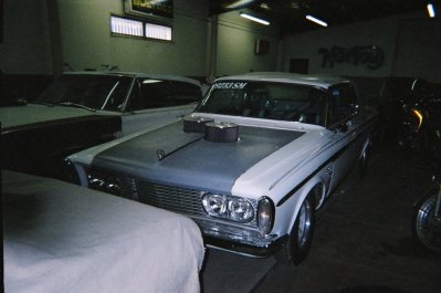
this is very cool , i've got a 63 fury that needs a floor , getting tired of wheel tubed drag cars . your building a sweet ride . just might barrow some of this mod for mine . i saw you using a wheel barrel tubb for the set back on the engine . did the same thing on a 60 d100 with a rb mod . but it didn't give enough room for removing the rocker covers . so i did a mod of a gmc 6 rocker cover to both sides for more room . but mt peddles are hang type , so i suck it back as well . this build is just stuff hanging out at my shop , here is a pic or two . might have to buy a few things for the fury . here is my 63 sport fury mw car , street/strip ride .

DCP01160.JPG DSC03266.JPG DSC04021.JPG DSC03594.JPG DSC03836.JPG DSC04066.JPG DSC03786.JPG 05190027.jpg
 

Attachments

  • scan0007.pdf
    420.5 KB · Views: 215
this is very cool , i've got a 63 fury that needs a floor , getting tired of wheel tubed drag cars . your building a sweet ride . just might barrow some of this mod for mine . i saw you using a wheel barrel tubb for the set back on the engine . did the same thing on a 60 d100 with a rb mod . but it didn't give enough room for removing the rocker covers . so i did a mod of a gmc 6 rocker cover to both sides for more room . but mt peddles are hang type , so i suck it back as well . this build is just stuff hanging out at my shop , here is a pic or two . might have to buy a few things for the fury . here is my 63 sport fury mw car , street/strip ride .

View attachment 421088 View attachment 421089 View attachment 421090 View attachment 421091 View attachment 421092 View attachment 421093 View attachment 421094 View attachment 421095

Sweet rides, thanks for sharing! That D100 is a wild looking beast.

Thanks for the kind words.

The wheel barrow firewall didn't make the final cut, it just wasn't sturdy enough and was causing more problems than it was worth.
 
Wow this is an impressive build, you have some serious skill!
 
Auto Transport Service
Back
Top