• When you click on links to various merchants on this site and make a purchase, this can result in this site earning a commission. Affiliate programs and affiliations include, but are not limited to, the eBay Partner Network.

'64 Fury Pro-Touring

I also used one of their harnesses, I gave up on getting any meaningful help from them and figured it out on my own... if you have any questions feel free to ask. One thing to always double check is some of the accessories, some like the electric fan circuit are fairly small wires, I only used them to wire the control side of the circuit then added relays tied directly to the battery to actually power the fans. I was very happy with mine but as you said about the instructions..... gotta figure it out on your own.
Hey Dev,

Thanks for the offer, I totally appreciate it.

By chance, I picked up a Painless instruction manual (at SEMA) a couple years back, WAY before I bought my AAW harness, so I could try and figure out what I'd need for re-wiring, and a couple things jump out:
  • AAW includes a 6 page instruction "manual" whereas Painless includes a 100+ page book. The AAW harness is a nice quality piece but 6 pages of instructions versus 100? AAW's instructions are absolutely minimalist (at best), so if you're choosing between the two kits this may be a deciding factor for you.
  • I haven't compared many of the wires between the AAW and Painless harnesses but those I've noticed are the same colors. Are both companies using the standard GM color coding for their harnesses? If so, then try and get your hands on a Painless instruction manual if you're using an AAW harness. Anyone who'd like me to check more wire colors should let me know and I'll be happy to do so.

I, like you, am using relays for all the items that need any type of significant power (fan, fuel pump, etc.) and using the AAW leads as the trigger only. Regardless of which wiring kit you use I have learned this is always a good practice. I'll be running 10 gauge leads from the power "out" side of my relays to the various accessories so resistance and heat should never be an issue.

One interesting thing I've never had to deal with before is a "ground trigger"; I've only ever used a positive triggers. While studying the various accessories I found the ground lead from the electric fan relay is connected to the engine mounted temp sensor, so when the sensor cycles between its 170 and 180 degree "on/off" temps it grounds the circuit and turns the fan on/off. Glad I'm taking my time and working through this stuff one item at a time!

LOTS to do in the next few days:
  • Install the front bars of the roll cage; cannot place various electrical components until I know where the cage bars will be
  • Front and rear master cylinders are on their way so I'm going to start running the hard lines along the chassis and to the calipers; I need these in place so I can figure out exactly where I want to place the brake pressure switch
  • Once those things are taken care of I can continue pushing forward with the electrical
Guess I should stop typing and get to work!
 
Hey Dev,

Thanks for the offer, I totally appreciate it.

By chance, I picked up a Painless instruction manual (at SEMA) a couple years back, WAY before I bought my AAW harness, so I could try and figure out what I'd need for re-wiring, and a couple things jump out:
  • AAW includes a 6 page instruction "manual" whereas Painless includes a 100+ page book. The AAW harness is a nice quality piece but 6 pages of instructions versus 100? AAW's instructions are absolutely minimalist (at best), so if you're choosing between the two kits this may be a deciding factor for you.
  • I haven't compared many of the wires between the AAW and Painless harnesses but those I've noticed are the same colors. Are both companies using the standard GM color coding for their harnesses? If so, then try and get your hands on a Painless instruction manual if you're using an AAW harness. Anyone who'd like me to check more wire colors should let me know and I'll be happy to do so.

I, like you, am using relays for all the items that need any type of significant power (fan, fuel pump, etc.) and using the AAW leads as the trigger only. Regardless of which wiring kit you use I have learned this is always a good practice. I'll be running 10 gauge leads from the power "out" side of my relays to the various accessories so resistance and heat should never be an issue.

One interesting thing I've never had to deal with before is a "ground trigger"; I've only ever used a positive triggers. While studying the various accessories I found the ground lead from the electric fan relay is connected to the engine mounted temp sensor, so when the sensor cycles between its 170 and 180 degree "on/off" temps it grounds the circuit and turns the fan on/off. Glad I'm taking my time and working through this stuff one item at a time!

LOTS to do in the next few days:
  • Install the front bars of the roll cage; cannot place various electrical components until I know where the cage bars will be
  • Front and rear master cylinders are on their way so I'm going to start running the hard lines along the chassis and to the calipers; I need these in place so I can figure out exactly where I want to place the brake pressure switch
  • Once those things are taken care of I can continue pushing forward with the electrical
Guess I should stop typing and get to work!
Ground triggered relays are realy nice for safety concerns like wiring a push button into your shifter, it shorts you don't get shocked which is why your horns are wired that way. Relays don't care if it's 12V or ground that's switching it.
 
Oh boy . . . is that looking good . . . . Really love the way that's looking ! ! !
 
Another long day at the shop and seemingly little progress to be shown for it thanks to a silly mistake :BangHead:
In order to get the location of a number of electrical items, like the high-beam switch, etc., I needed to install the front bars of the roll-cage because these follow the A-pillar down to the floor and land right where the switch would normally be. No big deal, just a log of slow, tedious fabbing up, right? Yeah, not so much.

Here's what I did:

Drivers side - measured where the hole in the floor needed to be, cut a 2" hole, then used the hole location to line up the floor plate and locate where the new support would be located and how long it needed to be:

IMG_0457.jpeg

Once I had the measurements figured out I fabbed up the cross-member. Yes, I dressed the welds before installing.

IMG_0456.jpeg

I dropped the leg of the roll-bar through the hole in the floor, lined it up with the marks I'd made previously, and welded the bar to the cross-member. Once they were 100% solid I slid the cross-member up into place and made a couple tack welds to hold it in place while I re-checked the alignment.

IMG_0458.jpeg

Once everything checked out I went ahead and burned in both the cross-member and the rear of the roll-bar tube (it mounts to the roll-over hoop behind the seats), so here are some shots of the bar once it was installed:

IMG_0459.jpeg


IMG_0460.jpeg


IMG_0461.jpeg

Notice I not only welded the down-tube to the cross-member but also to the floor plate, which in turn is welded to the floor. This solidly ties the floor/body to the roll cage adding more rigidity as well as safety.
This side of the car took all of Saturday but I figured I'd learned some lessons and today (Sunday) would go more smoothly/quickly, which it did, for a while.
I figured out it would be much easier to line up the location for the hole in the floor if I used a plumb-bob, something I did not do on the driver side, that is until you do something silly like forgetting to level the car BEFORE using the plumb-bob! The nose of the car was about 3" too high so the hole in the floor was about 3" too far to the rear, and before I noticed the difference in locations (front to rear) I completely fabbed up the cross-member and floor plate! What a waste of 4+ hours! I had to go back, re-measure, re-cut, re-weld, etc., etc., etc., the entire cross-member and tomorrow I'll have to patch the floor! No, I'm not happy with my bad self, I really should have caught this error long before I did. Either way, here's the passenger side:

Cross-member AFTER updating it:

IMG_0463.jpeg

Yes, it needs to be cleaned up before it gets installed.
Here are some shots of the car with both bars in place, though the passenger side is only set in place at this point:

IMG_0462.jpeg


IMG_0464.jpeg


IMG_0465.jpeg

I'll be back at the shop first thing tomorrow so I'll have the bars completed and hopefully will have moved on to the braking system by that point, then back to the wiring.

See ya!
 
Been keeping plenty busy on the Fury but the visible results are pretty sparse, just lots of progress that's pretty much outta sight.

Got the second down bar solidly mounted but forgot to include a shot of the floor repair, which came out real nice:

IMG_0466.jpeg


IMG_0467.jpeg

Once the down bar was in I began work on the brakes. This is the first time I've used Nickel-Copper tubing and a combination of -3AN (37 degree flare) and "IF" (inverted 45 degree flare) fittings, and wow, is the Ni-Cop pliable! It bends with virtually no effort at all. I haven't seen any downsides to using it so I'm hoping for the best. Here are a couple pix of my first lines and their install at the diff housing:

IMG_0468.jpeg


IMG_0469.jpeg


IMG_0470.jpeg


IMG_0473.jpeg

I got the line run from the diff to the firewall but am waiting for some 90 degree fittings before I move on. In the meantime, while I have the car jacked up, I'm adding some insulation matting to the underside of the floor, above the mufflers. The insulation, along with the multiple layers of spray on insulation, should help reduce the heat soak.
Taking today off but I'll be back in the shop tomorrow.
 
Been working on the Fury steadily since the last post and finished up all the brake lines, mufflers/insulation installed, as well as fabbing up a mount for the remote reservoirs (pix later), so here are some pix of the progress.

I must be the slowest worker on the planet because I can't imagine it would take anyone else a couple days to install the insulation and mufflers, but that's exactly what it took me. I mean, I get it, every piece I install on the car is custom made, there are VERY few off-the-shelf pieces I can use, but this insulation just seemed to drag on forever! Oh well, here are a couple shots.

I folded "expanded metal" into a tray of sorts, then turned the tray upside down and slid it up into the area where the muffler lives, but since the exhaust tubing runs through the frame rails there isn't much room, hence the need for the insulation. Once the insulation and "tray" were in place I had to figure out how to keep them there, so I drilled holes in the floor and used threaded inserts, into which I screwed in pan-head bolts with allen heads and fender washers. The pan-heads are really low profile so they worked out well and didn't cause any interference.

IMG_0475.jpeg

Yea, there are clamps installed on the exhaust and everything is buttoned. The mufflers are tucked way up into the floor pan so the bottoms of the mufflers themselves are just about even with the bottom of the frame rails, making for a super clean look (and a hot butt!). Here are a couple shots:

IMG_0476.jpeg


IMG_0477.jpeg

With the insulation and mufflers in place I dropped the car down and got back to work on the brakes. I started by working on the pedal installation and the bulkhead fittings that lead out of the car. Here's a pic of the pedals after the lines were run:

IMG_0478.jpeg

Since I don't know what trans or throw-out bearing I'm going to run I can't order a master cylinder, that's why there's an empty space next to the brake cylinders.
Then I moved on to the engine compartment and got the lines run, including braided steel that runs from the frame rail to the calipers.

IMG_0479.jpeg

The canister on the right side of the picture is my Moroso Accumlator, which has an electric switch so I don't have to mess with opening and/or closing the valve at startup. The remote reservoirs will be mounted outboard of the Accumulator so they'll be really hidden from view and help keep the engine compartment free from clutter.

IMG_0480.jpeg

Yes, that's a coupler in the line. Full disclosure: I screwed up and had to extend the line that runs over the trans tunnel to the passenger side. At some point I'll probably buy more line and make a new one but for the time being, I just wanted to get it finished.

IMG_0481.jpeg

Like I said before, it's shocking how little progress you make when every little thing you need to install has to be hand-made. Oh well, tomorrow I'll be back at it making something else!
 
I hear you on the time it takes to get something done. The 51 Chevy truck that is my current work project sucked up 1 1/2 days to make a fan shroud from scratch. From measuring, plotting, making a cardboard template, transferring to aluminum sheet, cutting the material out, folding the flanges on the brake, welding the corners, punching holes for the fans/nutserts/mounting holes, louvres, flaring the fan hole openings and ending with the final piece. I hope thats not a compression union you are using on your brake line.
 
I hear you on the time it takes to get something done. The 51 Chevy truck that is my current work project sucked up 1 1/2 days to make a fan shroud from scratch. From measuring, plotting, making a cardboard template, transferring to aluminum sheet, cutting the material out, folding the flanges on the brake, welding the corners, punching holes for the fans/nutserts/mounting holes, louvres, flaring the fan hole openings and ending with the final piece. I hope thats not a compression union you are using on your brake line.
Hey Carl,

Terrific seeing you during SEMA, thanks for stopping by again as well as for the great product info!

LOL, glad to know it's not just me working slowly, I really feel like age has caught up to me; maybe I'm not as old and/or slow as I thought!

Absolutely no compression fittings in the brake system, every connection is either AN or reverse flared.

Take care,

BW
 
Whew! Photo looked like a compression unit. I don't think its age as much as it just takes time to get stuff done. Experience helps but still we can't get it done as fast as we want.
 
A little catch-up is in order; I finished the brake line install but didn't have a picture of the remote reservoir mount or installation so here are those:

IMG_0483.jpeg

As I mentioned before, I haven't purchased the clutch M/C yet because I don't know what the piston size needs to be but as soon as I do it can mount immediately.
The washer, welded to the drivers side end, is the outer mounting point. The reason I used a fender washer is because this end of the mount doubles as part of the hold-down system for the inner fender, which is really evident in the second pix below.

IMG_0484.jpeg


IMG_0485.jpeg

In order to get back to the wiring I need to be able to install the dash, but with the new down-bars added to the roll cage I had to modify the dash. This was probably the most nerve-wracking thing I've done in a long, long time so I purposely took a lot of time and nibbled away at the cuts instead of going for it all at once. In the end I probably had the dash in and out of the car about 20 times but the results were well worth the time and effort.

IMG_0486.jpeg

As shown above, not only the top of the dash interfered, the bottom did too, so I had 4 points of interference to contend with at the same time. Not only does the "U" channel at the bottom of the dash add strength to the dash itself, it also forms a "doubler" for the lower mounting point, so cutting away the support (a must) left the mounting point very flimsy and weak, which I remedied by making my own doubler from 18 gauge steel and running about 8" up from the mounting point itself. I both rosette and spot welded the double in place as well as added a couple of spot welds where the mounts are welded to the dash. Probably overkill but I know it's not going anywhere.

IMG_0487.jpeg

Above shows my original layout lines. At this point I was dreading making that first cut but I knew I could fix it if I screwed something up.

IMG_0489.jpeg

Above is a shot of the drivers side lower after I made the first (of many) cuts as well as cut away the support mentioned previously.

IMG_0490.jpeg

The shot above shows the final shape of the passenger side lower and you can see the doubler tacked in place.

IMG_0491.jpeg

Due to the angle of the down bars I had to make the holes a bit larger than I would have liked, and the one mistake I made was cutting off a mounting pad from each end of the dash; it turns out I could have left them in place, so if you look closely at the picture above you'll see I have the pads welded back in place but not yet cleaned up (ran out of time).

IMG_0492.jpeg

Here's a view from inside the cabin and the fit is great, I'm really pleased with the outcome. Once I figure out where I am going to mount the high beam switch (next on my list of "to dos") I can begin running wires throughout the cabin to their final locations.
BTW, the dash will not be painted black, I'm going to paint it body color and use a black dash pad, which I think will be more in keeping with the stock Fury paint scheme. I'd love your thoughts and feedback on the idea.
 
Spent yesterday in the shop working on more details, including the dash, parking brake, and wiring, so here are a couple shots of my progress.

Installing the down bars for the roll cage created another issue, the parking brake, but I've had plenty of time to consider my options and decided on the simplest fix: I moved the brake mechanism inboard 1 1/2" using 3 tubular spacers and 2" grade 8 bolts. Easy, clean, and effective.

IMG_0493.jpeg

Now the foot pedal easily clears the down bar and after installing the drivers seat I know the pedal can be depressed without interference.

After I took care of the parking brake I did a bit of touch-up work on the dash. First I ground down the welds where I grafted back on a mounting point on each end of the front edge, then used Kitty-Hair to fill in the seam. I'll get a pix of that after I've smoothed it out.

With the dash sorted I could get back to the wiring, which still needs lots of attention.
First, I needed to add wires that ran from the auxiliary fuse/relay board to the high beams, low beams, fuel pump, electric fan, and power seats. I still have some additional wires to add for reverse and license plate lights but those will be simple, and I believe I can simply splice into the tail light leads in the trunk as opposed to running wires from the panel.
Once the additional wires were run I took a couple hours to finish separating the wires into bundles, specific to their location within the chassis as well as notating the relay use and wire color running from the relay to the powered fixture. Time consuming but I think it will all pay off if the electrical system performs like I want/hope.

The only real questions left, other than the reverse/license lights, are where to place the high beam switch and what type of switch to use? The down bar of the roll cage and relocation of the parking brake make it impossible to mount the switch in the foot-well so I'm going to have to mount a hand-operated switch somewhere. Any thoughts on what type of switch is necessary for high beam operation?

Here's a quick shot of the harness as it sits now:

IMG_0494.jpeg

More to follow!
 
Been a couple weeks since my last post but I've been working on the Fury non-stop; this electrical stuff is SLOW and tedious (to say the least) because there are so many things to do in order to run the wiring and terminate the ends, but I'm about 90% done with it so I wanted to post some pix.

Here are the front and rear harnesses:

IMG_0515.jpeg


IMG_0518.jpeg
I used convoluted split-loom throughout as opposed to taping it like the factory, though I did use 3M "99" series electrical tap at ever joint and termination.

Once the front and rears were done I finished looming all the engine compartment wires under the dash and ran the harness through the firewall as well as down the driver side kick-panel.

IMG_0519.jpeg

The mass of wires you see in the lower right corner of the picture are for the gauge cluster, high beam and light switch, all of which I'll mess with later.

I'm really fussy about keeping it neat and tidy under the hood so I took a bunch of extra time making sure I could run the harness hidden and for the most part, out of sight, running out through the firewall low and far to the outside so the fender and oil-accumlator hide most of the harness. I then ran the harness forward, inside the fender, using the fender bolts and cushion clamps to hold the harness up and out of the way.

IMG_0524.jpeg


IMG_0525.jpeg

With the harness in place I was left with a harness that is almost entirely out of sight, with only a couple small portions visible.

IMG_0522.jpeg


IMG_0526.jpeg


IMG_0523.jpeg

While building the harness I included a 12V power source for the CTS-V seats I'm using but I completely forgot to include wiring for the heater switches, so I'll be going back and figuring something out for those in the next couple days.
IMG_0516.jpeg
 
Been working on the Fury full time and making great progress, though it's mainly a bunch of mundane kinds of things that don't make for exciting pix, but here's what I've been up to.

After getting the wiring harness run I began working on the various lights, cleaning them up, whatever they needed to get them ready for installation.

I purchased a complete gasket set for the lights so mounting everything would be factory correct. The gasket set I bought was EXCELLENT so if you're looking for a good one PM me and I'll give you the name and contact info. The only thing the set didn't include were the black rubber seals that go around the outer perimeter of the lights, but I found some rubber U-Channel online that worked perfectly. Again, if you want/need some PM me and I'll give you the info.

IMG_0531.jpeg

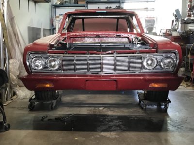
My front blinkers were a little worse for wear so I cleaned them up really well then painted the bulb "well" gloss black, followed by some Rust-O-Leum "Bright Coat Metallic", which comes out looking like chrome. I figured the new reflective paint would give off better light.
IMG_0542.jpeg

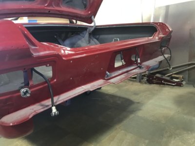
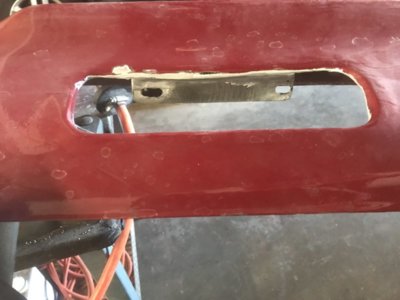
After painting the signals I went to install them on my glass bumpers and just didn't like the mounting tabs SC had molded into the bumpers, so I ground them off and made my own mounting tabs out of some sheet metal.

IMG_0533.jpeg


IMG_0534.jpeg

I bonded the tabs onto the back side of the bumper using Kitty Hair, and yes, I cleaned up the ugliness you see below.

IMG_0539.jpeg

The bumpers were never supposed to be painted body color, so no worries about all the nicks and scratches, I'll take care of them later (I'm going to use the same "chrome" Rust-O-Leum I used on the blinkers).

IMG_0540.jpeg

I've got much more to post but have to run. IMG_0541.jpeg
 
To finish up the wiring and lighting, I got all the rear lights mounted and tested. I used LED's for the brake/running lights as well as the reverse: I think the results have been worth all the effort!

IMG_0535.jpeg


IMG_0536.jpeg


IMG_0538.jpeg

With my decision to go with fiberglass bumpers I also decided I wanted to hide the mounting bolts, so I drilled a couple of 1/2" holes through blocks of furniture quality plywood (twice the layers than construction quality), counter sunk one side for the bolt heads, pounded the bolts through, then mounted the blocks (2 front, 2 rear) to the backside of the bumpers using a Kitty Hair. Once the Kitty Hair hardened I smoothed it down and laid a couple layers of fiberglass matting over the blocks and the surrounding area of the bumper.

IMG_0549.jpeg


IMG_0544.JPG


IMG_0546.jpeg

With the blocks in place I moved on to the mounts. The fronts are simple sheet metal boxes, which I seem to have forgotten to take a picture of (I'll add one later), but the rears are far more complex, using 3" x 1/4" aluminum stock, 1/8" steel plate, and 1/2" hardware. The rear mounts also allow for vertical as well as rotational adjustment, while the fronts are in a fixed position.

IMG_0551.jpeg

I am really pleased with the results, and now that the mounting is taken care of I can "chrome" the bumpers at any time.

IMG_0547.jpeg


IMG_0550.jpeg

With all the electrical (sans engine compartment) and bumper mounting taken care of I finally got to bolt in the inner front fender support panels (just behind the headlight buckets). I'll get a shot of these when I get back in the shop but I can't tell you how much they cleaned up the area as well as really solidified the lower front fenders. It's simple, but important, things like these panels that keep me motivated.

I'm taking today off to relax and re-charge but tomorrow I'll be starting on re-assembling the doors and rear window mechanical. I've never liked working on door mechs so I've put this off as long as possible, but I should be able to knock it out in no time. IMG_0547.jpeg
 
Looking good! Don't forget to toss some ground leads on those lights to the body/frame.
 
Looking good! Don't forget to toss some ground leads on those lights to the body/frame.
Hey Carl,

Added a ground on both the driver and passenger side of the rear harness and I’d already included them in the headlight harness.

Thanks much for keeping an eye on me!
 
Hey Bob! It's nice to see all the progress that you have made Sir. It's been a long haul but you have really built a terrific car there! I sort of lost track watching your updates back around the time you were struggling with the fibreglass.. You sure have stuck with it and prevailed!
 
Hey Bob! It's nice to see all the progress that you have made Sir. It's been a long haul but you have really built a terrific car there! I sort of lost track watching your updates back around the time you were struggling with the fibreglass.. You sure have stuck with it and prevailed!

Hey Mal,

Terrific to hear from you!
It’s been a hell of a struggle but I realized this weekend, I have finished all of the heavy fabbing work so most of the build revolves around assembly. I can’t tell you how good that feels!

Hope you check in more often.

Happy holidays to you, Carl, and the other supporters,

Bob
---
I will Bob! I was busy racing all summer and I've been working on another project for the winter now, but I'll check in, your at the exciting stage. See you around!
 
Auto Transport Service
Back
Top