• When you click on links to various merchants on this site and make a purchase, this can result in this site earning a commission. Affiliate programs and affiliations include, but are not limited to, the eBay Partner Network.

Ammeter ?

For what it's worth, automotive wiring can get real messy! (Meaning hard to deal with) Especially on later ones. That being said...

Glenwood is right, about checking the wiring in the column. Problem is probably in there, and to get to it, good chance you'll have to pull it, and tear it down, to actually 'fix' it.
Good luck on it!
I was wondering how they fished the switch cable through the column. Really you think the column would need to be disassembled to replace the ignition switch?
 
I was wondering how they fished the switch cable through the column. Really you think the column would need to be disassembled to replace the ignition switch?

It may not be the switch itself. The wiring may have rubbed through the insulation along the shaft or at the opening. First open the connector to visually inspect the connection terminals and whatever wiring is visible. If it was sparking there will be blackened wire someplace. You can then test for a short to ground but it may not be detected once you move the wiring around.
The wire terminals would have to be popped out of the connector body to remove the harnesses. It is easier to do with the column out of the car. Take care to note each wire colour and its position on the connector body if you go that far.
 
Agree as well. Most likely short to ground in the column. I'm guessing the ignition switch is on the column in 1970? Pull it out with the wiring, if you let the smoke out of the harness the issue will be evident.

Also, you will need to order some replacement smoke...
Smokekit2.jpg
 
Agree as well. Most likely short to ground in the column. I'm guessing the ignition switch is on the column in 1970? Pull it out with the wiring, if you let the smoke out of the harness the issue will be evident.

Also, you will need to order some replacement smoke...
View attachment 548415
LMO I need a 50 gal drum of that **** threewood lol.
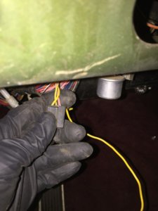
OK I found the short! It was the yellow wire from the switch getting pinched in the column.
12FD3D77-14B0-4B0B-B2A0-9EC7EA3144FA.jpeg
 
Great that you found it. Now, what to do with it?

Yes, it's possible for you to cut out the bad part of the wire, and splice it back together. Needs to be done right, so no problems later. Leave the Mickey Mouse stuff out...solder, or a good crimp, and a round of tape. And, while your in there, look things over good, so there's no other surprises.
If that does cure part of your problem, you lucked out! Sometimes not that easy.

You said you had a burned out fusible link? Only way to fix those, is replace them, cut the old one out, and splice in the new. But...a problem somewhere else in the wiring, is what caused it to burn. There's a good chance you've found it, but won't hurt to check the main circuits, before you hook things back up.

btw...that pink wire...going to the driver's side kick panel. Guessing, it goes toward the back of the car, via under the sill plate. Should figure out what made it cook!
 
Yes miller I spliced and soldered a yellow wire same gage in and used shrink tube. That was simple however that line goes to a connector that is not plugged in and i see no place to connect it. If anyone has any clue where this connection goes I would really appreciate it!
A8B4F255-CA26-4912-9120-8E0CE6692F1F.jpeg
FEEE15EA-0E0E-4AEB-8BEA-21EAB4253EA9.jpeg


8DD05925-8389-491F-A2C3-85287AC6D9FE.jpeg
 
Yes miller I spliced and soldered a yellow wire same gage in and used shrink tube. That was simple however that line goes to a connector that is not plugged in and i see no place to connect it. If anyone has any clue where this connection goes I would really appreciate it!
View attachment 548674 View attachment 548675

View attachment 548673

If I had to guess I would say ignition lamp relay. I only have a 1969 shop manual but I believe pink is acc lights and yellow is courtesy lights. Here is a link of a relay with what looks like the same pinout...
https://www.ebay.com/p/NOS-Mopar-Ig...lay-Relay-2889565-Cuda-Charger-GTX/1722241373
 
If I had to guess I would say ignition lamp relay. I only have a 1969 shop manual but I believe pink is acc lights and yellow is courtesy lights. Here is a link of a relay with what looks like the same pinout...
https://www.ebay.com/p/NOS-Mopar-Ig...lay-Relay-2889565-Cuda-Charger-GTX/1722241373
That looks like it! Thanks!! It would make sense since I the spades line up and there is not place that it plugs into. $40 lol for a can with probably a resistor and capacitor in it lol. Not sure why a delay is needed for a dummy light. Either way it looks like this module is non-essential.
 
check at your local Mopar dealer for the 2889565 and I bet you'll find it on $20 rate. they were the same up to 90s Cherokees ( XJ Chassis )
 
STANDARD MOTOR PRODUCTS RY300 {#2889565}

at rockauto... $11.29

AIRTEX/WELLS 1R1158

at rockauto $11.45
 
ebay got those on $13-25 rate for same ones. ( the $13 ones plus $6 on shipping ), But I bet rockauto shipping charges will barelly get $3 for ship one of those.

I THINK these parts are not listed by application, but search by PN ( like I did ). Or check your local Mopar dealer. Last time I knew about them it was listed on $19 or so. Local Mopar dealers in Venezuela have the same conection with the parts list all around Northamerica dealers.
 
Well that wire that burned up behind the dash appears to be a red-trace and according to the schematic it ran from the +bat Red ign1?) in the fuse box to the start circuit junction of (harness in the driver kick panel.

According to the schematic it runs to the junction of the horn, alternator, headlight relay and the ammeter.
No dis-respect meant, guy. On these forums, never know who your talking to.
Non taken miller! I know there are some sensitive folks on here but not me. I just want to learn and have fun....
 
I was able to determine that the wire that melted behind the dash is in fact colored red-black trace. Its the non-batt side of the ammeter. Its not a very heavy gauge wire but schematically is the supply wire to the fuse box for that point??

It looks like this went to the fuse box VBAT+ IGN#1? There is another wire at the fuse box that shares this junction/node and it is a heavy wire and it goes to the headlight relay Red. That is a heavy guage wire....and is currently hot somehow.

The red-trace burned up wire went from the fuse box across the dash to the driver side kick panel into a harness (darn).

Schematic shows that it goes into (via the harness) a main junction/node (not sure where the node is).
This node includes:
  1. Ammeter black
  2. Horn relay violet
  3. Alternator black
If this red-trace wire is not there which is currently the case and if the terminal on the fuse is already at 12V hot then what did this wire do? The headlights and horn work.

anyway I don't expect anyone to have the answers to this unless they are very familiar or adept at the wiring on these cars. I obviously have my work cut out to figure all the electrical issues out. I still need to know why I get no cranking when I try to start the car from the ignition switch. I can crank with a remote starter so I know that's inside the car....
 
Sounds like you are describing the original unswitched “Batt” feed to the fuse box. Coded as “Q3-14R*” in the ’70 FSM. 14 gauge wire that runs from a wire weld splice in the dash harness charge circuit (alternator side of the ammeter) to the fuse box. If the insulation is burned but the conductor is intact, it will still feed the fuse box. If not, the headlights and horn feed from the same wire weld splice but on separate wires, L1-16bk* & H1-16v.
 
Here is a simplified diagram showing how your car is wired (ignore the additional fusible link). Notice all current runs through the ammeter and through 2 connections on the bulkhead. And the factory splice supplies several components so they will all show hot.
car.jpg
 
Here is a simplified diagram showing how your car is wired (ignore the additional fusible link). Notice all current runs through the ammeter and through 2 connections on the bulkhead. And the factory splice supplies several components so they will all show hot.
View attachment 548964

Thanks guys your awesome!

72Roadrunner GTX thanks yup the red wire with black trace was not only without insulation but frayed and no longer connected to anything but headed towards the fuse box.

It looks like from Threewoods schematic and mine that it provides power to the ignition? This would explain two things.
1. the shorted yellow ignition line I found in the steering column burned out this line.
2. This being the supply to the ignition would explain why I get nothing when I turn the key.

This does beg the question of why does my headlights and horn still work without this line connected? Looking at the scematic it looks like that red-trace line supplies that node (weld splice) 12V from the unswitched VBAT.

Also where is this splice I hear they often fail...???????
 
pointing out to a straight wire between alt and batt via starter relay, so getting the power from batt side instead alt side

the deal on the original system is ALL the power goes through the ammeter, hence called full load ammeters. 70% of the ppl bypasses it ( mostly of them based on unintentional ignorance after a tipical failure caused by underrated charging system by Chrysler ) jumping the system with a link wire between alt and batt. This makes allmost unusefull the ammeter, being everything spliced from everywhere without any consistent power direction to be read by the ammeter
 
Last edited:
Auto Transport Service
Back
Top