• When you click on links to various merchants on this site and make a purchase, this can result in this site earning a commission. Affiliate programs and affiliations include, but are not limited to, the eBay Partner Network.

Can of rusty worms

Most of the stock housings I've done are 5 degrees up. 64 housing should have been narrower than the 70. A 64 won't take a standard flange axle shaft. Did it have tapered bolt on flanges on the shafts? Also anybody that's really tried to stuff a wide tire/wheel will find that the tire/wheel is seldom in the center of the wheel wells even with the perches centered.
Doug
 
Those headers look sweet!! How's the fit around the torsion bars?

On pinion angle, you want it to equal out when giving it the gas. So -3 degrees and +3 degrees =0. If you set it like this at rest once the rear end winds up it will put you out again as the rear will put you closer to +6 degrees. I would think you would be better setting the rear angle at 0 degrees to account for windup which would put you at -3 and +3 under load.

Seems to be plenty of room around the t-bars and steering box. I'm impressed with the fit of these 2" pipes so far.

That seems logical to me, but how can the wrap up angle change be determined and what are the tolerances before snapping the u-joint or something else? The original rear was pointing up about 5 degrees which would only worsen with hard acceleration from that tired 230hp poly. Can't imagine how much twisting will go on after effectively doubling the hp and increased torque. I tried the spicer calculator but I don't understand how it will tell you what your pinion angle should be as it expects you to know what your driveshaft angle is before you alter the pinion angle. I'm missing something here
 
Most of the stock housings I've done are 5 degrees up. 64 housing should have been narrower than the 70. A 64 won't take a standard flange axle shaft. Did it have tapered bolt on flanges on the shafts? Also anybody that's really tried to stuff a wide tire/wheel will find that the tire/wheel is seldom in the center of the wheel wells even with the perches centered.
Doug

Doug, the original housing looks like 5 degrees up like you've seen, but is that correct for the trans tail pointing down 3 degrees or do you see a different angle there usually? According to the housing widths chart I've seen, the 64 is wider than 62-63 and 65-70. This 64 is definitely wider than the other which I believe is from a 70.
Regarding the axles, Dr Diff can make flanged axles to fit these early tapered axle style housings. Mine had the tapered axles. KryslerKid just did the conversion on his original 62 housing. The conversion used green style bearings though and I'm not sure there is enough room for inner seals.

from the suspension section sticky:
B BODY
'62-'63= 53 1/4" (And '64 Max Wedge)
'64 = 55 5/8" (Exc. Max Wedge)
'65-'67= 54 1/4"
'68-'70= 54 15/16"
'71-'74= 57 7/8"
 
I put mine 4* nose down, so when you drop the hammer, the pinion will rise, then everything will be where it should and not vibrate.
 
I don’t recall, but with my 4 speed and Dana 60, there are zero vibrations.
 
I may have seen the axle wrap numbers in the Mopar Chassis book. I'll check when I get home.
 
Doug, the original housing looks like 5 degrees up like you've seen, but is that correct for the trans tail pointing down 3 degrees or do you see a different angle there usually? According to the housing widths chart I've seen, the 64 is wider than 62-63 and 65-70. This 64 is definitely wider than the other which I believe is from a 70.
Regarding the axles, Dr Diff can make flanged axles to fit these early tapered axle style housings. Mine had the tapered axles. KryslerKid just did the conversion on his original 62 housing. The conversion used green style bearings though and I'm not sure there is enough room for inner seals.

from the suspension section sticky:
B BODY
'62-'63= 53 1/4" (And '64 Max Wedge)
'64 = 55 5/8" (Exc. Max Wedge)
'65-'67= 54 1/4"
'68-'70= 54 15/16"
'71-'74= 57 7/8"
 
I don't believe that sticky is incorrect. Lots of misinformation out there. The early housing can take late style axles with a green bearing. There is not enough depth for the bearing and a seal. 3 degrees down at the tail is unusual for stock mounts. I agree when its all said and done (if you're going to race it) the pinion on a leaf spring car needs to be 4-5 down from having the trans output and rear pinion center lines parallel.
Doug
 
Thanks kid. I decided to stick with this 70 axle since it is a little narrower than the 64. Trying to determine a reasonable pinion angle value is an interesting challenge. I put the housing back in the car tonight and set it on the new perches. Maybe I'll button it up and drop it on its wheels tomorrow night if I have the energy.

found this little blurb on an old post from some other site. Thought it was interesting...

Suspension specialist Dick Miller bases pinion angle settings on horsepower. Miller likes to see 2 degrees of negative pinion angle (relative to the driveshaft) on applications in the 400hp range, 3½ to 4½ degrees in the 500hp to 650hp range, and up to 7 degrees with 700 horses or more. Miller also acknowledges that the greater the pinion angle, the more horsepower the driveline will consume, but it’s a compromise that must be made. Miller notes that these angles are merely guidelines, and each individual combination should be fine-tuned.

essentially, I would have to install the driveshaft and check all three angles and pivot the axle to correct the pinion angle, whatever that is supposed to be.
 
I've been missing out on your progress somehow. Looking real good!

I used the Doug's Headers also and installed them the same way you had to. I really like them.

It's been awhile since I messed with pinion angles. I lowered a truck awhile back and wedges had to be used to correct the angle. Wish I could remember what I learned but there is a formula.

Keep up the good work :thumbsup:
 
Your rear end swap reminds me back in the day when I had a '64 Polara 500. I found a Dana out of a '68 Charger for $150 (those days are long gone) 456 gear and it bolted right up. Even the e-brake cables worked with it. I had 10" Cragar SS with H50s and they were really tight under there. Well after installing the Dana I actually had more room. That's when I found out just how wide the original rear was. I had a driveshaft made up and that 383 really came alive! Fun times...
 
Found this in a post from Dr Diff regarding setting the pinion angle:

"Pinion angle is the relationship between the pinion centerline and the transmission centerline. It is not relative to the ground nor to the angle of the driveshaft.
Ideally, you want the pinion to become parallel to the transmission under a load, so you point the pinion downward a few degrees when the vehicle is resting on its suspension to compensate for pinion wind-up.
In other words, make the pinion parallel to the transmission as a base line, then roll the pinion downward 2-4 degrees and weld the perches. This is how a 2 joint driveshaft is designed to work." Cass

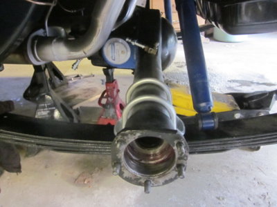
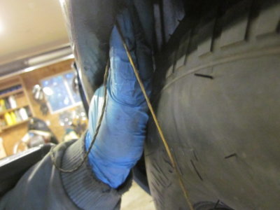
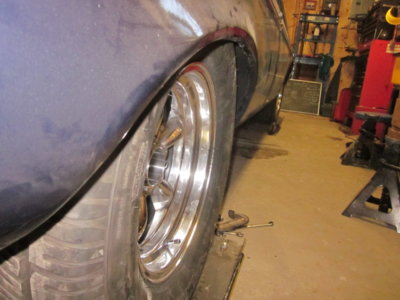
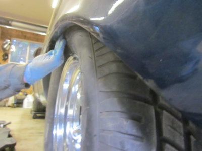
I managed to set the housing on the new perches and snug the u bolts after slipping the axles in and installing the wheels. I used a plum-bob to check space between the tire outer edge to the outer wheel well hump. Had to bump the assembly over a couple of times, but now there's fairly equal space on both sides and the wheels turn freely.

Before I dropped the car down onto the wheels, I checked the perches and pinion angle that I had eyed up. The perches were level and the housing sat at approx 5 degrees, just like the original 64 housing. Once on the wheels, I checked the trans tail which was 2.5 degrees down and the pinion was at 0.5 degrees down. That 3 degree difference should be about right and place the pinion in parallel with the trans centerline while under load, if I understand this correctly. Hoping to tack them in place tomorrow and remove it all again to be welded.
 
This method takes a little more time initially. But as my buddy always says. "If you don't have time to do it right the first time. You will always have way more time doing it the second time". Good job.
Doug
 
Thanks Doug.
I managed to tack the perches but I almost made a mistake. I double checked and the differential was a half degree up, not down. It's tight squeezing my gut under there trying to look at angles and easy to get mixed up.
So I had to loosen it all up and rotate it down. I added a degree so that the full sweep is 4 degrees for some anticipated hard acceleration. :D
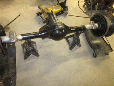
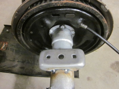
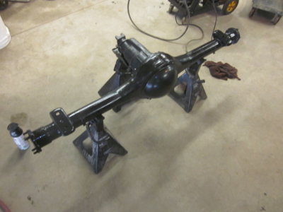
Pulled the axle back out last night, to be welded today. Hopefully welding perches won't warp the housing.

Meanwhile, I designed a two piece fan shroud and had it waterjet cut out of aluminum. I'll be fitting it to the rad this weekend so it can be welded. I'm pulling the motor soon so i want to get the shroud fitted before I do. Pics to come later...
 
Here's a few pics. Turned out pretty good with clearance on both sides.

IMG_5113.JPG IMG_5117.JPG IMG_5120.JPG IMG_5123.JPG
 
Auto Transport Service
Back
Top