• When you click on links to various merchants on this site and make a purchase, this can result in this site earning a commission. Affiliate programs and affiliations include, but are not limited to, the eBay Partner Network.

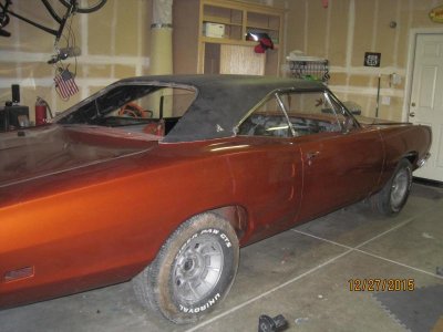
My 69 Coronet project

Ok......lets see the gouge.
OK, you asked for it. Don't say I didn't warn you.

- - - Updated - - -

I wasn't going to ask, probably miserable enough without showing it off to us haha. Put a sticker over it!

It's like a Quentin Tarentino movie - don't go if you can't stomach the carnage..lol
IMG_3202.jpgIMG_3203.jpg
 
Last edited:
Got a roller - sort of

Spent today wrapping up the front suspension. Slammed in the new .96 torsion bars. First we bolted the upper control arms to each spindle and the lower shock mount to the LCA's then raised the suspension to clock the torsion bar to the LCA. If the bars were 1.0" or larger I don't know if they would clear the headers - as it is there's maybe 1/8" clearance. Didn't need to massage the headers at all, but man, it's close.

Torqued down most of the suspension bolts. For some reason I didn't tighten the zerk fittings when the suspension was out of the car - would've saved some time 'cause with the headers in the way it took a while to cinch them down. So the car's a roller -sort of. Bolted on the one wheel but the spare tire wouldn't clear the hub on the rotor. Now I have a three legged stool. Can't torque down the LCA or strut rod bolts until the suspension is completely loaded. Going to have to get new tires and wheels sooner than later.

Probably going with 15" Magnum road wheels with beauty rims - Hawk's RR made quite an impression. Torque Thrust II's are still in the hunt. Tires will be 235 or 245/60/15 front and either 275/60/15 or 295/50/15 out back.

Still a lot of play in the torsion bar adjustment.
IMG_3198.jpg

Looks sort of Gasser-esque
IMG_3199.jpg
IMG_3200.jpg
 
Devin, when you met Maria on Saturday she was my girlfriend; on Sunday she was my fiancé.
I'll be hitting it hard now, only got 10 weeks.

Good luck buddy, Ive been with my wife now 43 years, married 38, i pray you have a ball with all this,,, i would love to do every thing over again, my lady and my cars!! :)... And your work is going good looking at all the things you've done... :happy11:
 
Congratulation

Congratulation on the engagement !

That's great news !
 
Good luck buddy, Ive been with my wife now 43 years, married 38, i pray you have a ball with all this,,, i would love to do every thing over again, my lady and my cars!! :)... And your work is going good looking at all the things you've done... :happy11:

Thanks Ron. I got me a good woman; sounds like you do too.

- - - Updated - - -

Congratulation on the engagement !

Thanks Khan. I didn't say anything at the Nats when I saw you guys 'cause it was going to be a surprise - and it was! I picked the engagement ring a few weeks before, hid it from her the entire trip until I popped the question on Sunday.
 
Great progress Rich! It is great to see the engine and front suspension right where it should be. I found that my suspension settled once I drove the car - yours likely will as well.

Glad my RR gave you and Maria some wheel options to consider. If you do get 15" magnum 500 style wheels, I suggest the Stockton manufactured ones, and not the Wheel Vintique brand. I heard that the latter rusted quickly. As far as rim and tire sizes, I went with 8" rims all around, and 245s for the front and 275s for the rear. With the car fully loaded and our Dad's in the back, even my 275s rubbed with large dips in the road. I wouldn't suggest bigger that 275s.

Electrical Wiring
This post is to explain how I added an extra power under my dash, while safely keeping the original Chrysler wiring and connectors. Rich wanted to do something similar to his car, so I have added a description of what I did in case others are interested too. The connectors below reference a 1970 Road Runner.

First, this assumes that you have replaced your alternator gauge with a Voltmeter (or if you are just going to disconnect and no longer use the alternator gauge). I am also assuming a max of about 70 Amps draw on a system and a more powerful alternator.

A stock system
First, it is important to understand a very high level overview of a stock system. Power, through a red wire connects from your battery to the starter relay power lug. A short fusible link then connects the starter relay to bulkhead connection J. Connection J is on the middle of the three connectors, which is the engine wiring harness. This connection powers a red 12 gauge wire that goes to one side of the alternator gauge. The other side of the alternator gauge is a black 12 gauge wire and this powers all your under dash electrical power needs. This black wire also exits the firewall at bulkhead connection P (also located on the engine wiring harness). Connection P goes directly to the alternator through a black 12 gauge wire.
So if your system is using more power than the alternator can provide, the alternator gauge shows discharging since the battery is providing extra power. If your alternator is charging the battery, the gauge will show charging. The key thing to understand is that both the red and black wires are 12v powered. The alternator gauge simply tells you the direction current is flowing.

Alternator
The first thing to do is to allow the alternator to charge the battery without passing through the alternator gauge. This is simply done by running new 10 gauge wire from your alternator BAT connection to the starter relay power lug. Carefully remove the old alternator wire from the engine wiring harness, bulkhead connection P. This old wire will be abandoned, and I would recommend that you fully remove it. The reason you are replacing it is simply to run a larger wire that can handle more power, but this is important so you can run the extra power safely.

You now need to replace the power source to the black wires under the dash. To do this, simply connect the starter relay power lug to the bulkhead connection P using a second fusible link. YOU WANT A FUSIBLE LINK TO PROTECT YOUR CAR FROM BURNING UP – DON’T JUST USE A STRAIGHT WIRE!

Alternator Gauge
Under the dash, disconnect the alternator gauge. Take the black connector and carefully wrap it up. It will have power on it, so it must be insulated, but do not connect it to anything.
The red wire can now be used to power your new under dash circuits. This wire should connect to a 12 gauge wire that will go to a separate fuse panel.

How the “new” system works
So now you have both power from the battery and the alternator connecting to the starter relay. This starter relay also has TWO fusible links that provide power to the car. The new fusible link added above powers all the stock wiring. The existing fusible link powers the red wire that now powers nothing except your new fuse panel. Add new circuits to this fuse panel.
This way, each of your fusible links can handle roughly 35 Amps and keep within the limits of the wiring that was originally supplied with your car. I would recommend that all your added circuits be connected to your new fuse panel. You likely will need a relay or two to create switched power circuits as well.

Good luck and I hope this helps!

Hawk
 
Hawk - awesome write up. I had started drawing a wiring diagram right after you left; I need to post it and get your input. You probably remember when looking at my dash that the black and red ammeter wires are soldered together so they just have to be cut apart. I was researching fuse blocks on Summit that other FBBO members had installed. They are designed to use a jumper wire from a switched circuit on the original block over to the new block. If I understand correctly, this eliminates the need for relays but the new fuse block is in series with the old, instead of your design that's on its own circuit protected by an independent fusible link.
The red 12 ga wire running between the bulkhead and the ammeter must be a "run" circuit, which is why relays are needed? Excuse the rookie questions, I'm still enrolled in Automotive Wiring 101.

No rookie questions - that's what the forum is for!

Yes, your ammeter wires will need to be cut apart or de-soldered, but that should be pretty easy.

The red 12 gauge wire running from the bulkhead will be powered all the time, even when the key is in the off position. This will allow circuits to be powered without the key on. Most likely you will want switched circuits that are only powered when the key is in the "run"position. To do this, you can power the relays from the old fuse block without issue. The relays themselves take very little power to trigger the relay, but you can still then provide the load from the new fuse block.

What I wrote above is probably confusing as hell. Let me draw up a small diagram and maybe that will make things a bit more clear. I'll work on that tomorrow, as it is now past my bedtime!

Hawk
 
Actually your description was very understandable. And 10-4 on the 12 ga wire.
 
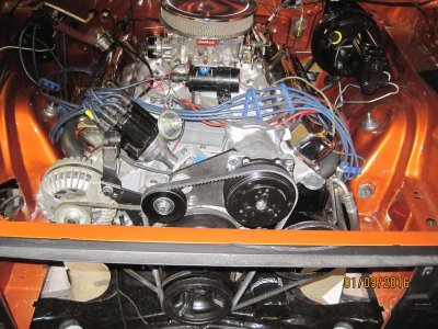
After dropping in the engine/trans I took a week off to prepare for and enjoy Christmas. Then it was back to the garage. Got a lot done over the course of a week - hooked up the torque converter to the flex plate, installed the drive shaft, carb, tranny linkage, fan belts, small odds and ends. The tranny linkage took some time to get back in - and not because of the headers. The shift rod goes into the tranny and then goes through a bushing thats attached to a bracket that bolts to the frame. Kinda like a Z- bar on a 4 spd. Not a lot of room to negotiate. Thank goodness I took dozens of pics before disassembly. Speaking of headers, the Dougs 452's fit real nice around the tranny linkage and kick down assy. Originally I was planning on going Lokar if the fit wasn't there but no need.

At this point I have a complete drive train from stem to stern for the first time in almost two years. As Hawk said earlier, now its the million little things that have to be done before the car is ready.
IMG_3214.jpg

In hindsight there were a few things I could have done before dropping the body on the K frame. Like install the speedo cable and grommet in the firewall - more difficult with the engine in. And we could not get the tranny cooler lines snaked through the engine compartment. Should have rested them on the K member before mating the trans to the engine. So now we are either going to have to bend the hard lines to try to fit or go with flexible hose the whole way.

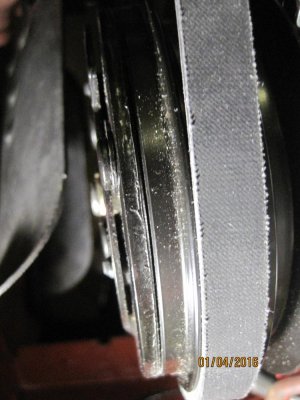
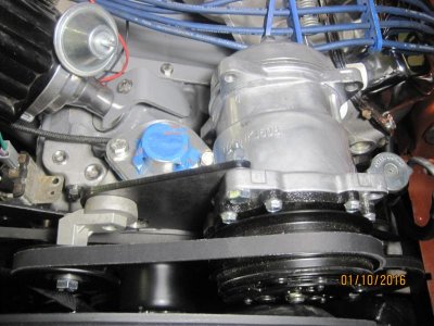
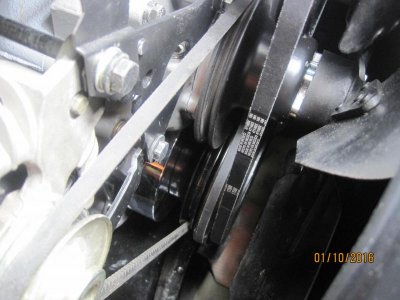
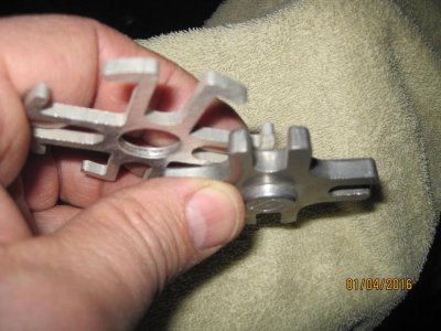
To the front of the engine - the new A/C compressor pulley lines up perfect. The kit comes with a pulley that attaches to the crank pulley - you substitute 3 of the 6 bolts. A small problem with the fan hitting the front of the compressor. Again, the kit comes with two spacers - the first one was still too thin, had to go with the thicker one. And you can see in the photos it only leaves about a 1/4" gap. But now the fan bolts are too short so I have to stop off at Lowes before the weekend to pick 4 up.
IMG_3215.jpgIMG_3216.jpgIMG_3218.jpg

Once the fan is on, next comes the radiator and shroud. It's starting to feel like a real car again.
 
Hi Rich,

Nice progress!

As you saw with my car, my fan and pulley setup is a bit goofy since it has the low mount "hidden" compressor. Your setup is far superior to mine, so I don't think you will have near the issues I had getting my compressor to work quietly and reliably. Having said that, take the time to get all this stuff to line up well, or you may likely have squealing belts and hassles down the road...

Engine looks bitchin' sitting between the fenders! :headbang:
 
If you don't mind I'd love to see more pics of your bracket and pulley setup. I'm hoping to add A/C this winter and looking at options, I already have the Sadden compressor and would love to use some of what I have instead of buying all new. Also hoping for a setup that puts 2 belts on the alternator too.


Coronet is getting close, bet your getting really excited with all the little pieces finally finding their home again! Looking great.
 
Quite a work in progress. Thanks for posting.
Thanks Roger. It's getting there.

- - - Updated - - -

Hi Rich,

Nice progress!

As you saw with my car, my fan and pulley setup is a bit goofy since it has the low mount "hidden" compressor. Your setup is far superior to mine, so I don't think you will have near the issues I had getting my compressor to work quietly and reliably. Having said that, take the time to get all this stuff to line up well, or you may likely have squealing belts and hassles down the road…


Engine looks bitchin' sitting between the fenders! :headbang:

I don't know Hawk, you're engine compartment is real tidy. Mine's getting cramped! The pulleys line up nice - Classic Air did their homework.

- - - Updated - - -

Hey Devin, I read your post after the radiator was installed so I couldn't get any more pics from directly in front. I took some more tonight; the lighting isn't very good so let me know if you need more detail and I can take more during the day.
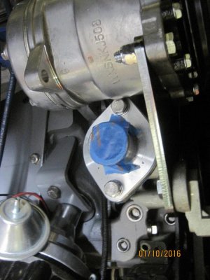
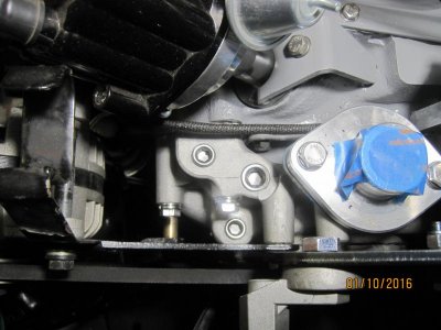
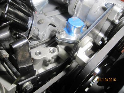
The compressor brackets use three water pump bolts - two by the p/s.
IMG_3236.jpg
The alternator bracket is sandwiched by the other compressor bracket. Oh, and ignore the wiring, haven't wired up the harnesses yet.
IMG_3235.jpg
The thermostat can't be removed without unbolting the compressor.
IMG_3234.jpg

IMG_3233.jpg

IMG_3237.jpg
Here you can see the fan spacer needed to clear the compressor.
IMG_3241.jpg
IMG_3238.jpg
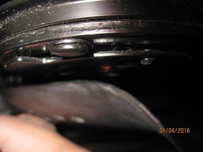
Two groove crank pulley (had to buy a new one, original was cracked). CA provides a pulley that fits inside the OEM pulley - remove and replace 3 bolts.
IMG_3240.jpg

IMG_3239.jpg

Let me know if you need any more.
 
Last edited:
Nice progress Rich!! Man you have been jamming on this project lately. It looks bitchin'. Hey I tried to PM you but your inbox is full. That thing going to be ready for spring fling April 23? I will be bringing my car for the first time.

- - - Updated - - -

By the way, don't forget to grease your suspension fittings like I did...
i got your text Dwayne; was in the garage most of the day. I'll have to attend to my Inbox and respond. The goal is to have the car road worthy by March 1st and drive down to Spring Fling; I'd like to go a day or two early and catch the Mailbu cruise. I really want to see your car too.
And thanks for the heads up on the fittings - they do need to be greased.
 
Yeah I will be going down two days early with Dennis for willow springs track day as well as Malibu cruise. When you are ready I can send the info for lodging. Congrats on the engagement too. I can confirm that you two are a great couple and she is a very cool girl. She's into the cars as much as you which is rare!
 
Where'd my engine compartment go?

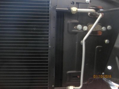
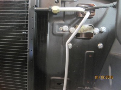
Running out of room. Dropped in the radiator/shroud. Installed the a/c condenser and hard lines. We had some extra time so even though the engine will be fired-up and broken in with the carb we installed the FiTech Fuel Control Center. The link gives more background; short version its a fuel sump for the EFI system to be installed at a later date. Wanted to mount it on the passenger side inner fender but with the radiator and alternator installed we ran out of real estate. So now it hangs from the rad support, however prelim measurements dictate the battery will have to be relocated. Early on in the project I had planned on relocating the battery to the trunk anyway; it adds a level of complexity I had decided wasn't worth it. Plans change.

http://www.forbbodiesonly.com/moparforum/showthread.php?98175-FiTech-efi/page3


The a/c condensor slid in like it belonged. My short sightedness led to the FCC being installed before the a/c hard lines; I almost blew brain when I saw that the lines went through the rad support opening right where the FCC was mounted. By sheer luck, raising the FCC about 1/2" created enough space for the lines to snake past. I usually don't get that lucky.
View attachment 301413

View attachment 301412
The rubber strip running across the lower opening is the OEM pad from under the carpeting. After ripping it out I'm finding 101 uses for it; here its an isolator for the FCC brackets.
IMG_3221.jpg
There's a lot going on in the top opening. Everything fits though. The FCC brackets are secured by six bolts; the top left fits through an unused OEM hole; the other five I had to drill.
IMG_3220.jpg
 
Thanks Rich, looks like a simple enough setup. My biggest concern is my alternator belt slipping. I really want 2 belts on it but should get an amp clamp on it first.... might not need the 100 amp alternator which would likely fix that problem.

That engine compartment is looking sweet, keep it up!
 
Auto Transport Service
Back
Top