• When you click on links to various merchants on this site and make a purchase, this can result in this site earning a commission. Affiliate programs and affiliations include, but are not limited to, the eBay Partner Network.

'64 Fury Pro-Touring

Hey Ed,

Yeah, I picked them up a few years ago; they were wrapped up and sitting in my front office. When I bought them they cost $500 but I bet they'd be less expensive now that newer V's are out.

Hope your pops is doing better.

Talk to you soon.

Bob, Really nice job with the seats. Did you take them out of your caddy or pick up another set? Those will definitely make for a comfortable ride in the fury!!!

- - - Updated - - -

Josh just said you had another set in the shop. I don't remember seeing them though.
 
Hey Joe,

The wiring for the airbags was removed while the seats were unpowered, so no chqnce of a blowout.

I didn't go into detail about the airbags but they were removed, after which I had an upholsterer make up a matching patch panel to put in place of the old air bag cover.

If you look at the previous page there's a picture of the seats taken from the passenger side, and in that picture you can make out the outline of the patch panel on the side of the seat back.

care full they have side airbags touch the wrong wire and boom
 
I bought all the replacement body panels from Sled City about 4 years ago and only touched them when I needed to do some kind of test fitting or alignment, but now I'm FINALLY getting a chance to hang some of them on the car.

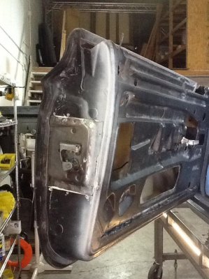
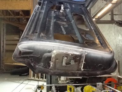
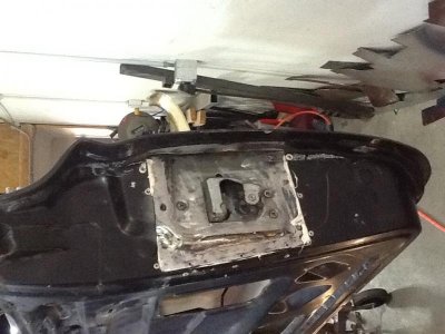
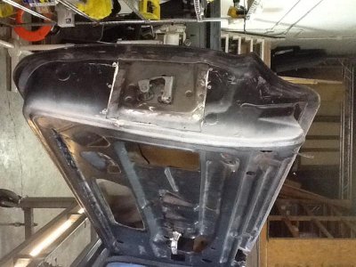
The first pieces I've messed with are the doors, which are easily one of the mos complex pieces of this puzzle. The doors are nothing more than hollow shells, no mounting studs, threaded inserts, slots, holes, NOTHING, so I've had to transfer every detail from the original doors onto the glass ones, and in some places cut areas out of the steel doors and bond them into the glass doors. This isn't a knock on Sled City, not at all, the pieces are stellar; they just take a LOT of work.

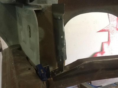
Here are a couple of shots of where I've grafted the striker/latch area from the steel door into the glass door. I used 3M panel adhesive and rivets, so they won't be coming lose any time soon.

image.jpg

image.jpg

I could have skipped this step and mounted the latch directly to the glass doors but I just didn't feel there would be sufficient strength in such a high stress area.

Below are pix of the doors closed and adjusted with all the handle and latch hardware in place.

image.jpg

image.jpg

Now that the doors are in place I'll begin mocking up the fenders, rad support, etc.
 

Attachments

  • image.jpg
    image.jpg
    78 KB · Views: 446
  • image.jpg
    image.jpg
    63 KB · Views: 456
  • image.jpg
    image.jpg
    78.1 KB · Views: 450
Dam this car is looking good keep up the good work going to love seeing this finished

PS removed the torsion bars from my car go to my link and check out what im puttin in
 
did yah load up the striker plate with epoxy paste before yo riveted it into the door and will you finish it up with some JB weld to smooth it out
 
did yah load up the striker plate with epoxy paste before yo riveted it into the door and will you finish it up with some JB weld to smooth it out

Hey Joe,

The panel adhesive is a two-part epoxy that auto mixes as it's pushed through the tube/straw. I ran a healthy bead around the perimeter of the striker plate, making sure there was ample epoxy in the rivet holes.

I haven't done any clean up at all, they are exactly as they were when I finished, but I figure I'll use either plastic body filler or a fiberglass/resin combination to give it a finished look.
 
WOW . . . doors looking great there ! ! ! More progress . . . love to see it . . . Thanks for the updates . . .

I knew something was missing . . . I didn't see any doodling on the parts ! ! !
 
I must say that looks allot better than the glass panels I've seen, nice job.
 
WOW . . . doors looking great there ! ! ! More progress . . . love to see it . . . Thanks for the updates . . .

I knew something was missing . . . I didn't see any doodling on the parts ! ! !

LOL, my Sharpies are STILL drying up! Must be the 106+ temps here in Vegas heating up the metal and sucking the life out of them. Maybe I should get some colored chalk?

- - - Updated - - -

I must say that looks allot better than the glass panels I've seen, nice job.

I've actually been pretty impressed with the quality of the glass parts but they are definitely race quality and the guys at Sled City told me that before I bought them. The fitment is definitely not what I got used to when I built my '70 Vette, but how many knuckleheads rebuild a '64 Plymouth as compared to Vettes?

- - - Updated - - -

My new Riv-nut tool arrived late last week but the time available to work on the car has been somewhat limited; regardless, I've been working on getting the doors mounted so I can then move forward and fab the fender mounts and rad support.

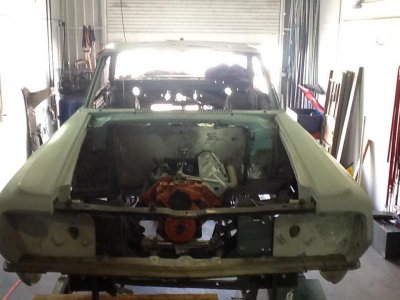
Here are the first shots I took of the initial trial fit of the fenders:

image.jpg

image.jpg

image.jpg

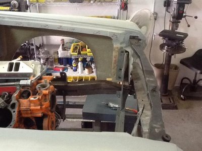
If the car had any kind of structure left I think the fiberglass parts would be a lot easier to work with; I would have numerous reference points to work from, but as it is I'm winging it for most of the pickup points. Luckily, and I don't even remember why I did it now (it's been 5 years or so) but before I dismantled the factory rad support and frame rails I welded tabs for lining up the fenders onto my chassis plate, making my job quite a bit easier than it could have been.

image.jpg image.jpg image.jpg
 
Riv-nut gun eh Bob? Haven't heard that word in a while. Seen them as a diesel apprentice back in high school, working for a Freightliner Dealer. You got a picture/link of what you bought?
 
Riv-nut gun eh Bob? Haven't heard that word in a while. Seen them as a diesel apprentice back in high school, working for a Freightliner Dealer. You got a picture/link of what you bought?

Hey Prop,

Yep, a Riv-nut gun :icon_eyes:
On the stock fenders there are quite a few weld-nuts used so in order to make my life easier I'm using Riv-nuts to duplicate what the factory did.

Try this link and let me know if it works: http://www.amazon.com/gp/product/B003TODXQW/ref=oh_details_o00_s00_i00?ie=UTF8&psc=1

BTW - by comparison to my Marson (which broke) the replacement was about 1/3 the cost and works really well; no complaints at all and I would recommend it.
 
Hey cool...A new tool! I'm gonna have to jump on that. Thanks Bob! Link works good. Looks pretty slick.
 
Wasn't it the Grateful Dead lyric that said "What a long strange trip it's been"? Well, that's been the story of my business life over the past couple years and it's continually getting in the way of my progress with the Fury, but this weekend I'll be diving head-long back into it and will have plenty of updates.

Be back shortly!
 
Good to here you'll be getting back to it.
 
nice to here I been hard at it with my valiant as well cant wait to see what you have done while you have been off
 
Hey fellas,

I spent hours working on the Fury this weekend and made some excellent progress, though not without some difficulties.

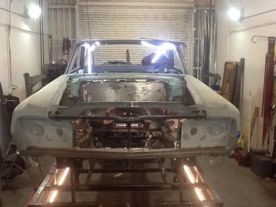
In my previous couple of posts you see the doors and fenders in place, but the fenders weren't really attached to much of anything; they were bolted at the door jams but the forward ends were resting on shims; what I really needed was to get the rad support in place so the fenders have a permanant, fixed point to bolt on to.

Since I still have the bumper filler panel and the hood latch support, both of which bolt between the fenders, I used these two pieces to set the fixed distance the fenders, then centered them on the chassis.

This picture shows various pieces of string strung between the frame rails and the center points marked. Another piece of string was pulled (at 90 degrees to the other strings), running along the center points towards the front of the car. This string allowed me to accurately find the center point of the bumper filler panel.
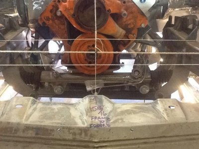
image.jpg

From there I had to set the fender height so I used my digital level sitting on top of a straight edge running between the fenders.​
image.jpg

But now is when the trouble began. I now had the fenders in place, level, and pretty much where they'd be at final assembly, so I decided to take some measurements at common points on both fenders, like the pointed tip and wheel arch.

Here are pictures of the measurements taken at the tips of the fenders; you'll notice the measurements are not the same.

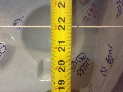
image.jpg

image.jpg

Wondering WTF I had done I used my digital level and checked the string running between the tips; I was within .1 degree.

Totally confounded I moved on to measuring the wheel arches:
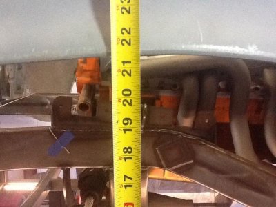
image.jpg

image.jpg

For the life of me I couldn't figure out what I'd done to knock the fenders out of alignment so I put my straight edge back across the fenders, and guess what; they were still level!

I spent the rest of Saturday trying to figure it out and the only thing I can come up with are errors creeping in during the manufacture of the fenders. The fenders are an assembly of smaller pieces bonded together and if errors begin to creep in the fenders won't be symmetrical.

I decided the best course to follow would be to use my established centerline and level lines and build the rad support around those known measurements.
 
So once I made the decision to ignore the fender measurements and go with the centerline and heights Ihad established I took what was left of the existing rad support (it had lots of rot) and salvaged the sides and upper rail and began piecing a new one together.

With the fender width established and locked down using the bumper fill plate and latch support I fabbed up some small "L" brackets to span the distance between the frame rails and the rad support sides, spot welded them in place, then tacked the base of the "L" to the frame. Now the fenders have a completely stable attachment point and this allowed me to move on to the upper rad support bar.

Here are the side supports:

image.jpg

image.jpg

Once the sides were mounted I took the top bar, put it in place, and wouldn't you know it, it was too narrow (side to side). This top rail, like the bumper filler and latch support came directly out of the car, and yeah, I had to cut the original support apart, but I never had to mess with the width, so for me this was just another indication of how the fenders were fabbed together with REALLY lose tolerances!

I took the upper rail, cleaned up the mating surfaces where it would meet up with the side supports, and tacked the driver side in place. Now I had a 5/8" gap on the passenger side so I used a cut-off wheel, cut the top bar in half, bolted the top rail to the passenger fender, tacked it to the vertical support, then filled the 5/8" gap in the center.

Here are some shots of the rad support in place along with the bumper filler and latch support:

image.jpg

image.jpg

- - - Updated - - -

I've got a series of pictures of the front suspension all mocked up but they're in my PC at work so I'll post them later, but here's a bit of a tease; this is what the tire/rim combo looks like mounted on the suspension. To say I'm stoked is putting it mildly!

image.jpg

Once the rad support is finished (I need to fab a lower cross-member for the rad to sit on) and I play around with the roll cage I can take the car off the chassis plate and put it on the rotisserie, which will then allow me to finish weld many of the areas that are only tacked as well as patch the MANY small areas.

After all these years I can't believe I am nearing the point where the car goes on the rotisserie!

image.jpg image.jpg image.jpg image.jpg image.jpg
 
Auto Transport Service
Back
Top