• When you click on links to various merchants on this site and make a purchase, this can result in this site earning a commission. Affiliate programs and affiliations include, but are not limited to, the eBay Partner Network.

Don's 1969 Charger Restoration

Don, I have a factory repair manual which has the body/frame dimensions detailed in an illustration as well as written procedures for checking frame alignment after collision. If you can get one of these manuals you will have the complete dimensions that a frame shop would use for body alignment. this method is more accurate than trying to measure an old car body that is probably sagging from rust or bent from years of use. My factory repair manual is for 66 b bodies , I think it would be different than your car but another member may be able to fax you a copy correct for your project? Keep up the good work!
 
Don....its been a little bit since i visited your thread and have to say....holy crap dude....you are like 20 spot welds away from having that car into its individual components! It will be all new when you are done. Work looks good and keep up the progress.

I am sure between the pile of us around here we can keep your dimensions on track.
 
Don you can substitute that beer for what ever you like !
 
Man oh man Don, you're making great progress, I gotta get going on mine again soon.
Thanks CharGer, I try to spend 2-3 hours everyday after work plus Saturdays that is to say inbetween "life"

No fair Don. I have to come over here to keep up with this project. The rust primer looks good and it must feel great to have it look new and clean. Keep it rolling. Great work.:icon_winkle:
Thanks Stevearino, and your right it does feel better not having to look at rust!

Don, I have a factory repair manual which has the body/frame dimensions detailed in an illustration as well as written procedures for checking frame alignment after collision. If you can get one of these manuals you will have the complete dimensions that a frame shop would use for body alignment. this method is more accurate than trying to measure an old car body that is probably sagging from rust or bent from years of use. My factory repair manual is for 66 b bodies , I think it would be different than your car but another member may be able to fax you a copy correct for your project? Keep up the good work!

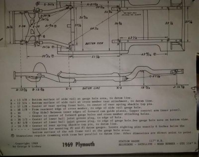
I have this.. which I used but a lot of the dimensions need the front suspension on. WHICH IS NO GOOD TO ME! Some of the dimensions are from the edge of the hole and point to point (not horizontal).
What I really need are dimensions from the gauge holes from a top view.
When I built my jig I used the obvious dims, and everything lined up pretty good.
But It's just that nagging feeling I would like to get rid of!

plymouthframediagram.jpg

Don....its been a little bit since i visited your thread and have to say....holy crap dude....you are like 20 spot welds away from having that car into its individual components! It will be all new when you are done. Work looks good and keep up the progress.

I am sure between the pile of us around here we can keep your dimensions on track.
Thanks kb67,
See above.... I would like to remove that nagging feeling and be ABSOLUTLY sure everything is where it should be!

Don you can substitute that beer for what ever you like !
Thank you
 
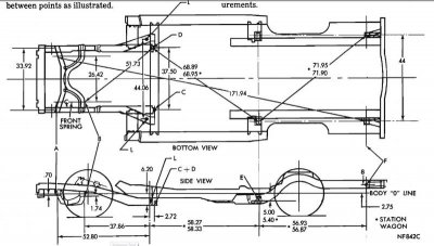
So you are looking more for something like this.

69Charger-Coronet Frame.jpg

This is out of the 69 Charger / Coronet manual
 
It looks n seems complicated but it really isnt. When i did mine i made sure i had the proper datum line n car was level. I checked all side to side measurements for all points listed.than i did the x pattern starting from the rear n using the datum hole for alignment, once done there i than did the x pattern from datum hole on rear frame to datum hole on front n than continued to k member using the x pattern on both front n rear holes n making sure the front rails where properly spaced.this seem to work for me i guess time will tell.but with a mock up off k member n rear springs everthing went back together quite easily
 
So you are looking more for something like this.

View attachment 207485

This is out of the 69 Charger / Coronet manual
Thanks BB61,
I have this also, and used some of the numbers like the 44.06 dim on the front clip.
But it really does not give me all of the numbers I want!

It looks n seems complicated but it really isnt. When i did mine i made sure i had the proper datum line n car was level. I checked all side to side measurements for all points listed.than i did the x pattern starting from the rear n using the datum hole for alignment, once done there i than did the x pattern from datum hole on rear frame to datum hole on front n than continued to k member using the x pattern on both front n rear holes n making sure the front rails where properly spaced.this seem to work for me i guess time will tell.but with a mock up off k member n rear springs everthing went back together quite easily

With the way I am doing it, all of the numbers from the torsion bar forward will be good, because I replaced the entire front clip.
And I have the rear frame rails set to the 51 1/8 dim.
Also on the rear frame rails I have the 36-3/4, 35-1/2, and 37-1/4, all held.
I know that all of my heights are good 13-5/8, 6, 6, and the 16-7/8!

What would make me feel better is if I had a diagonal dimension (x dimension) like the 64-1/16
If I knew this was a good number, that would help.
Also if I had an overall dimension from the rear crossmember to the front radiator support would help! And which dimensions are important? and Tolerances?
 
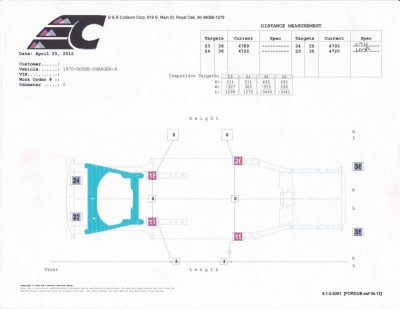
Don, When I took my car completely apart I was pretty naive and didn’t use a jig. I got some of stuff wrong. But then I made a jig and used the same chart you have in your 8.25.14 post. I had to make some adjustments and redo some things. Also being concerned after I got it together enough and put the old suspension on it I took it to the body shop that will do the final work and paint my car (they do a lot of restoration work) to have them put is on their frame jig and measure it up. It came within factory tolerances. They only took two sets of measurements (overall length along the frame and cross dims from front and rear end of the frame). They told me these old cars had a lot of play in the tolerances and there was a lot that can be done with the body panels to take up any issues in the frame (previous owner did a lot of this). I’m not saying to ignore your gut feeling, but if you are good on all the dimensions in the diagrams from the recent post here you should be good to go. I looked up what I got from the body shop and the image below is what I got (measured level I presume). I don’t know where the targets are located they measured to. I also took a measurement from the front K frame bolt hole (with a threaded stud in the hole) to the front of the front leaf spring mount and it was less than a 1/16” out of square. The measurements in the image are in mm. Give me a call if you have questions on this.

page-0.jpg
 
A-pillar work

Time to update this thread.....
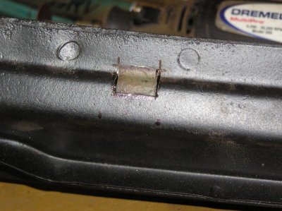
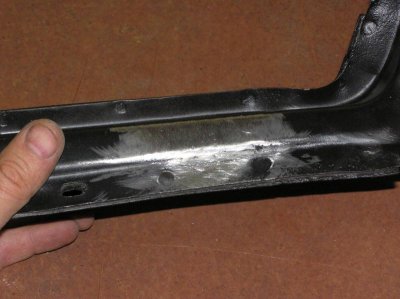
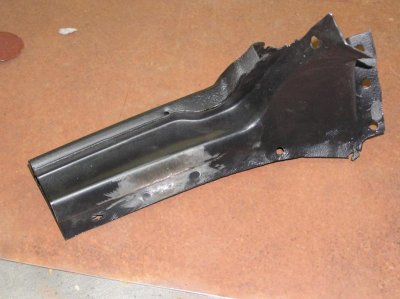
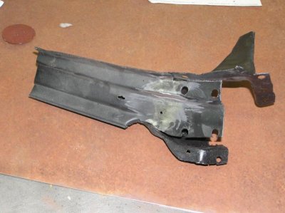
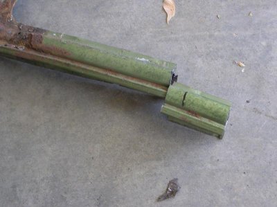
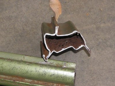
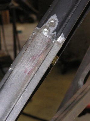
Had a couple of bad spots on the a-pillar donors so I patched them

P1010021.jpg

P1010020.jpg

P1010022.jpg

P1010023.jpg

P1010024.jpg

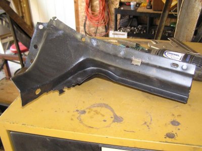
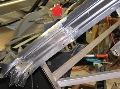
Next I cut off another section from the a-pillar donor.
P1010031.jpg
P1010032.jpg

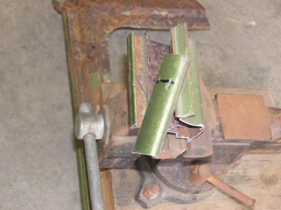
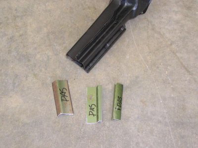
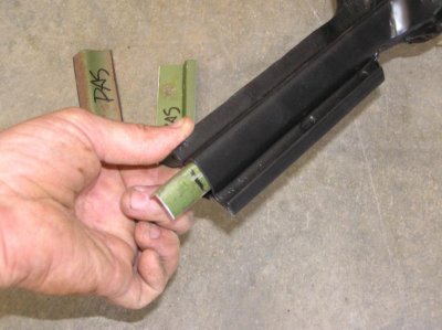
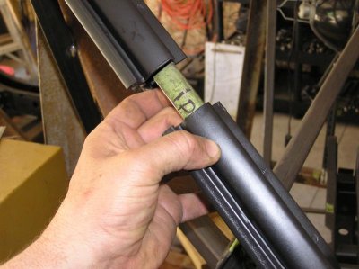
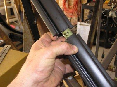
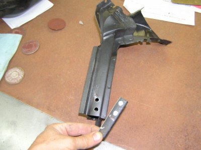
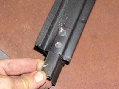
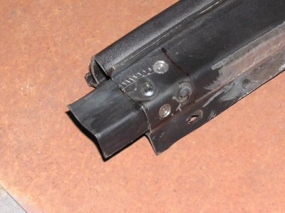
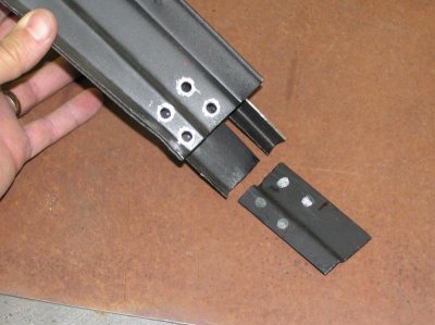
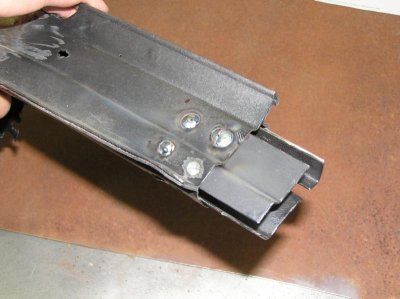
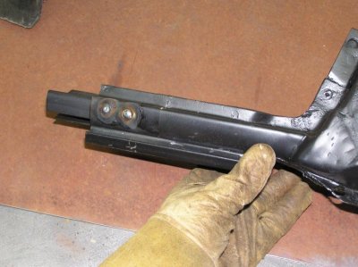
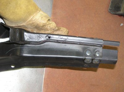
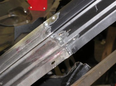
Then I cut out some tabs that will telescope inside the A-pillars
Kinda like 1962polara mentioned back in post #240
Don't know what it's called in metal work ..but wouldn't a scarf join be stronger than a straight join?

View attachment 213536


I do luv your work though!

P1010033.jpg
P1010035.jpg
P1010036.jpg
P1010037.jpg
P1010038.jpg

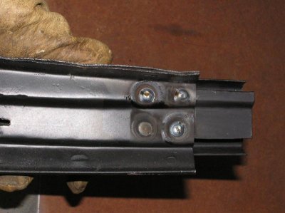
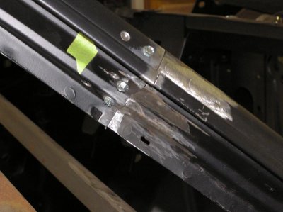
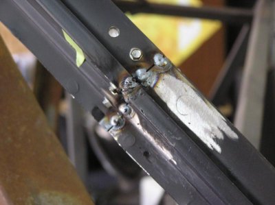
Drilled some holes, and welded the tabs in

P1010050.jpg
P1010051.jpg
P1010052.jpg
P1010053.jpg
P1010054.jpg
P1010055.jpg
P1010056.jpg
P1010057.jpg

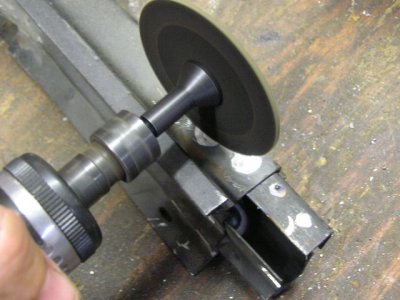
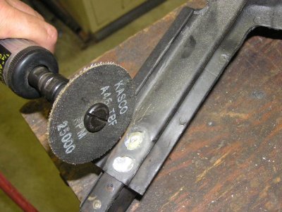
Here is what I used to grind down the welds to just above, then I switched to a 90 and blended them in

P6120059.JPG
P6120060.JPG
 
I also like the fat cut off wheels for knocking down spot welds (work great and don't make so much heat). Looks like a strong joint to me, keep up the good work!
 
Don your doing some really great stuff here on this project! It appears you really know how to make some good welds, im still learning and i think im getting better lol, but this your doing is top notch!
 
Thanks much for the link!!! Im going to enjoy this one myself and hope to learn...
 
Attaching the sectioned A-pillars

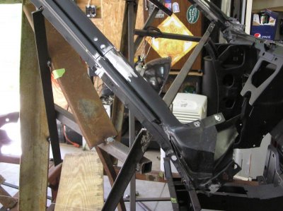
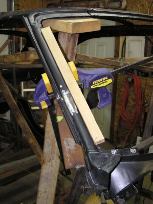
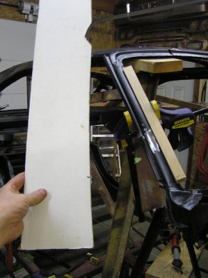
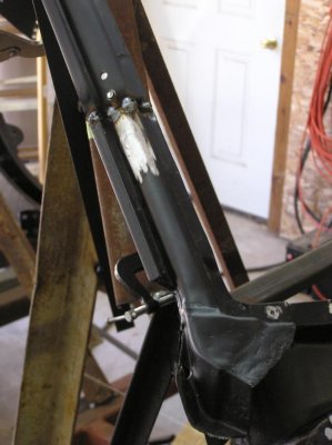
Used some screws to temporarily hold the pillars. This helped for adjusting the alignement

P6130063.jpg

P6130064.jpg

P6130065.jpg

P6130066.jpg

P6130067.jpg

P6130068.jpg

I used this piece of oak (that was dead straight) to help alignment
Also notice the 2x6 piece of wood. I used this to spacer the roof up above the cowl

P6130069.jpg

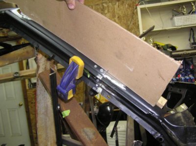
Then I used this template I had mad earlier to check alignment the other way

P6130070.jpg

P6130071.jpg

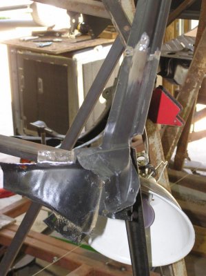
One I liked the alignment I tacked it in place

P6140072.jpg

P6140073.jpg

P6130063.jpg P6130064.jpg P6130065.jpg P6130066.jpg P6130067.jpg P6130068.jpg P6130069.jpg P6130070.jpg P6130071.jpg P6140072.jpg P6140073.jpg
 
Ummmmmmmmmmmmmmmm........... Still looking for the car haha. Your nuts:icon_eyes:
 
That work looks great, and that link is helpful if we get thru the boeties Fender anyway lol, Im just kidding, I started reading and looking at the pic and got called away but i will bet it will be helpful to us who are nuts enough to do what were doing! Thanks again..
 
Don, garage journal.com is a great resource for metal working advice from a professional, thanks for the tip!
 
Want to make another pair of those lower rear window corners Don? Your old ones look really good compared to mine, left is not there at all just fragments left where the spot welds were! You are doing an awesome job on your resto. Keep patching and welding eventually you'll have a charger again !
 
Wow! You are doing great work.:headbang: I enjoy following your progress and learning from you.
 
Auto Transport Service
Back
Top